
Pipe-expansion tip cone and pipe-expansion method of the same

A technology of pipe expansion and top cone, applied in the field of pipe expansion top cone, can solve the problems of surface wrinkles of pipe fittings, increase production cost, reduce the service life of pipe expansion top cone, etc. The effect of a single deformation amount

Inactive Publication Date: 2017-04-19
常州良旭车辆配件有限公司
View PDF9 Cites 1 Cited by
  • Summary
  • Abstract
  • Description
  • Claims
  • Application Information

AI Technical Summary

Problems solved by technology

[0003] The existing expanding tube top cone is usually a one-piece conical structure. During the deformation process, one-step operation method is often used. Therefore, a sufficiently large axial thrust is required to overcome the resistance during the moving process of the expanding tube mold. At the same time, due to the expansion tube The process is too fast, and the single-processing deformation of the pipe fittings is large, which may easily lead to uneven metal extension and deformation of the pipe fittings, resulting in wrinkles or even cracks on the surface of the pipe fittings. Similarly, the expanding pipe top cone bears the corresponding reaction force during the deformation process. Because the expanding pipe top cone is The integral design causes the surface stress concentration on the top cone of the expansion tube to be concentrated and cannot be released, and the surface of the top cone of the expansion tube is prone to wrinkles or cracks, which greatly reduces the service life of the top cone of the expansion tube, increases production costs, and affects production efficiency and product quality

Method used


Image

  • Pipe-expansion tip cone and pipe-expansion method of the same
  • Pipe-expansion tip cone and pipe-expansion method of the same
  • Pipe-expansion tip cone and pipe-expansion method of the same

Examples


Embodiment 1

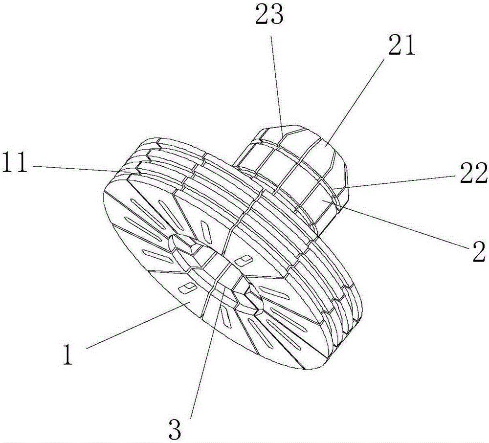
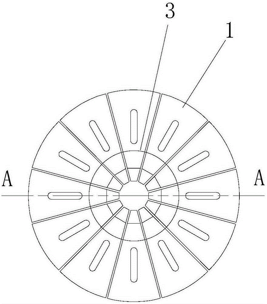
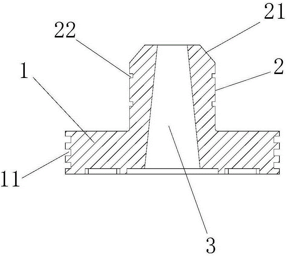
[0024] Example 1 Figure 1 to 3 As shown, the top cone of the expansion tube of this embodiment includes 12 L-shaped expansion tube monomers, each expansion tube monomer includes a fan-shaped portion 1 and a fan-shaped column portion 2, and the inner side of the fan-shaped column portion 2 is a conical arc The outer surface is a cylindrical arc surface, and 12 expander units are joined together in a centrally symmetrical manner to form the top cone of the expander; the fan-shaped part 1 of each expander unit constitutes an annular cover plate, and each expander unit is fan-shaped The inner surface of the cylinder part 2 cooperates to form a tapered hole 3, and its outer surface cooperates to form a deformed part. The outer tapered tube expansion shaft is inserted into the tapered hole 3, and the tapered hole 3 is inserted into the expansion tube shaft. , The top and the sector of the single fan-shaped column part 2 of the expanding tube swing around the elastic contraction ring...


PUM


Abstract

The invention relates to a pipe-expansion tip cone and a pipe-expansion method of the same. The pipe-expansion tip cone includes a plurality of L-shaped pipe-expansion single bodies, wherein each pipe-expansion single body includes a sector portion and a sector cylinder portion; the inner side surface of the sector cylinder portion is a conical cambered surface; the outer side surface of the sector cylinder portion is a cylindrical cambered surface; the plurality of L-shaped pipe-expansion monomers are combined together in a central symmetrical manner to form the pipe-expansion tip cone; the bottom of the sector cylinder portion of the pipe-expansion monomer is in cup joint with an elastic contraction ring; a conical hole is formed through coordination of the inner side surface of the pipe-expansion monomer; an external conical pipe-expansion shaft is coordinatively plugged in the conical hole; and the outer side surface of the middle part of the sector cylinder portion is provided with a circumferential buffer slot which is convenient for timely releasing of the surface stress of the pipe-expansion tip cone during the pipe-expansion process. When the pipe-expansion tip cone is used, a method of multiple deformation is employed, so that single time of deflection of a pipe piece can be reduced; cracking of the pipe piece can be avoided; and the shape of the orifice of the pipe piece after multiple times of pipe-expansion can become more uniform.

Description

Technical field [0001] The invention relates to a mold, in particular to an expanding pipe top cone. Background technique [0002] As we all know, such as the pipe fittings used in the pipelines of automobiles and air conditioners, the pipe ends must undergo the process of expanding or shrinking the pipe to be formed. In the pipe expansion process, the end of the pipe can be processed into the required shape through the cooperation of the clamping device (so-called clamping die) that clamps the pipe fitting and the top cone of the pipe expansion. [0003] The existing top cone of the expanding pipe is usually an integrated conical structure, and the one-step operation method is often used during the deformation process. Therefore, sufficient axial thrust is required to overcome the resistance during the forward process of the expanding pipe. The process is too fast and the deformation of the pipe fittings in a single processing is large. It is easy to cause uneven metal extension ...

Claims


Application Information

Patent Timeline
IPC IPC(8): B21D39/20
Inventor 潘金良
Owner 常州良旭车辆配件有限公司
Learn More