
Synchronous orbit satellite relative dip angle remote correcting method based on line-of-sight measurement

A synchronous orbit satellite, relative inclination technology, applied in the directions of artificial satellites, space navigation equipment, space navigation aircraft, etc., can solve the problems of distance estimation error accumulation, lack of tracking spacecraft relative distance information, etc.

Active Publication Date: 2017-04-19
BEIJING INST OF CONTROL ENG
View PDF5 Cites 11 Cited by
  • Summary
  • Abstract
  • Description
  • Claims
  • Application Information

AI Technical Summary

Problems solved by technology

Since only the relative pointing information of the target can be obtained, but the relative distance information between the tracking spacecraft and the target is lacking, the distance estimation error along the direction of the spacecraft line during the filtering estimation process accumulates significantly.
This deficiency is inherent in relative navigation methods that use only line-of-sight measurement information (Chari, R.J.V.. Autonomous Orbital Rendezvous Using Angles-Only Navigaiton[D]. Massachusetts: Massachusetts Institute of Technology, 2001)

Method used


Image

  • Synchronous orbit satellite relative dip angle remote correcting method based on line-of-sight measurement
  • Synchronous orbit satellite relative dip angle remote correcting method based on line-of-sight measurement
  • Synchronous orbit satellite relative dip angle remote correcting method based on line-of-sight measurement

Examples


Embodiment Construction

[0041] Below in conjunction with accompanying drawing and specific embodiment the present invention is described in further detail:

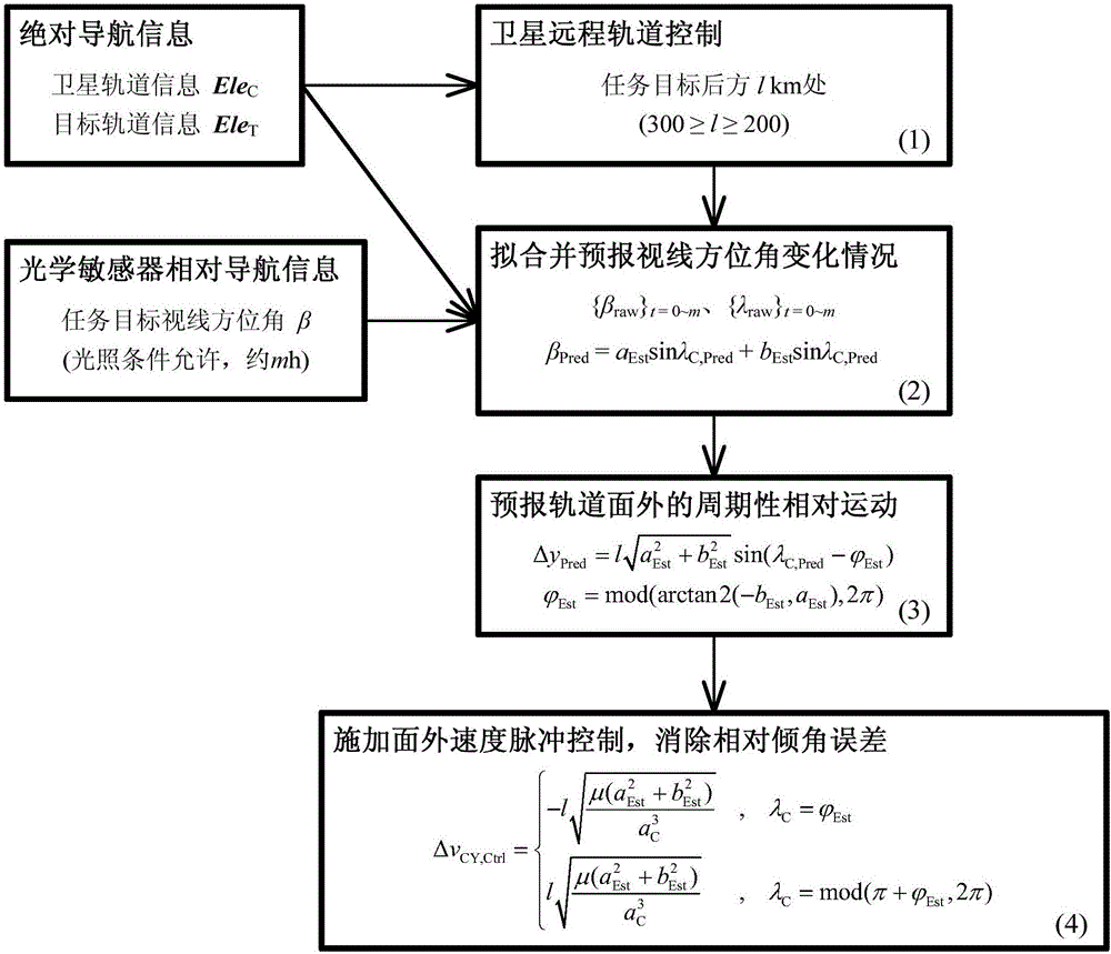
[0042] The method of the present invention mainly consists of 4 steps. The specific flow diagram of the method, such as figure 1 shown.

[0043] Step (1) Satellite remote orbit control

[0044] Geostationary orbit satellites provide absolute navigation information based on the ground measurement and control system (orbit information Ele C and mission target orbit information Ele T ), carry out remote orbit control on the geostationary orbit satellite, eliminate the relative semi-major axis, relative eccentricity, and relative inclination vector deviation between the mission target, and control the relative flat longitude, so that the geosynchronous orbit satellite is parked at 1 km behind the mission target ( 300≥1≥200).

[0045] Orbit information Ele of geostationary satellites C , refers to the semi-major axis a of the geostationary orbi...


PUM


Abstract

The invention discloses a synchronous orbit satellite relative dip angle remote correcting method based on line-of-sight measurement. The method comprises the following steps: at first, carrying out remote orbit control on a synchronous orbit satellite through absolute navigation information provided by a ground measurement and control system, and directing the synchronous orbit satellite to a remote mooring point in the rear of a task object; then, through relative navigation information of an optical sensor and the absolute navigation information provided by the ground measurement and control system, and in combination with typical motion features of the relative orbit of a spacecraft, adopting the Least Squares method to fit and forecast variation of a line-of-sight azimuth angle; further, forecasting the periodic relative motion outside an orbital plane between the satellite and task object in combination with the nominal distance at the mooring point; and finally, carrying out velocity pulse control outside of the orbital plane on the operating satellite at the mooring point to eliminate relative position error outside of the orbital plane caused by the relative dip angle to avoid the situation that the task object is lost because the task object is beyond the field of view of the optical sensor, so that the satellite can rapidly and accurately approach the task object.

Description

technical field [0001] The invention relates to the field of relative navigation and control of long-distance non-cooperative targets based on line-of-sight measurement information, in particular to a long-distance correction method for relative inclination of synchronous orbit satellites based on line-of-sight measurement. Background technique [0002] In missions such as spacecraft on-orbit service, the line-of-sight navigation method using optical cameras as the main detection method is considered to be an important means for non-cooperative autonomous relative navigation of spacecraft. The relative navigation equipment for line-of-sight measurement has many characteristics such as light weight, low power consumption, and compact structure, and it belongs to passive detection. The application research in the field of autonomous rendezvous in space is constantly emerging. [0003] The problem of relative navigation of long-distance non-cooperative targets based on line-of-...

Claims


Application Information

Patent Timeline
IPC IPC(8): B64G1/24B64G1/10
CPCB64G1/10B64G1/242
Inventor 王楷朱志斌常建松魏春岭何英姿汤亮王大轶
Owner BEIJING INST OF CONTROL ENG
Learn More