Liquid filling equipment

An equipment and filling pump technology, applied in liquid distribution, conveying or transfer devices, special distribution devices, packaging, etc., can solve the problems of low efficiency, time-consuming, slow speed, etc., to improve efficiency and shorten vacuuming time , Improve the effect of vacuuming speed

Inactive Publication Date: 2017-04-19
CHERY AUTOMOBILE CO LTD
View PDF8 Cites 3 Cited by
  • Summary
  • Abstract
  • Description
  • Claims
  • Application Information

AI Technical Summary

Problems solved by technology

[0005] The vacuum pump is used to evacuate the vehicle pipeline, the speed is slow, and the liquid filling speed is constant during the filling process, which is time-consuming and inefficient

Method used


Image

  • Liquid filling equipment

Examples


Embodiment 1

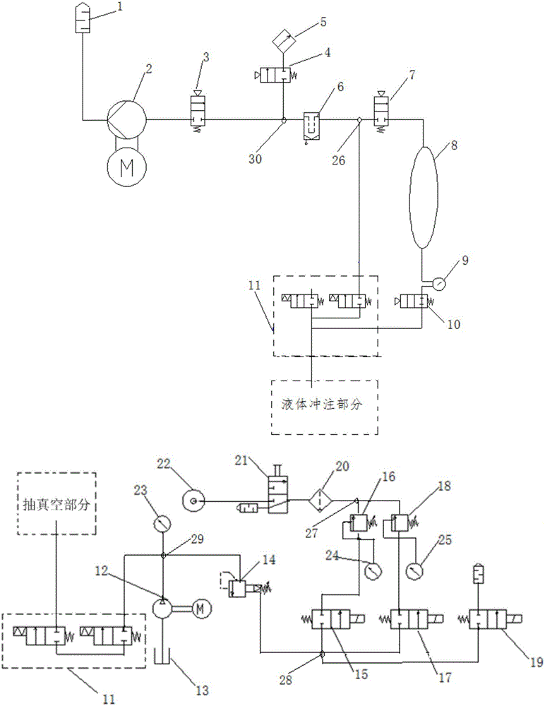
[0030] This embodiment provides a liquid adding device, such as figure 1 As shown, it includes vacuum pumping part, filling part and filling gun head 11, wherein,

[0031] The vacuum part includes a vacuum pump 2, a vacuum tank 8, a vacuum pump on-off control valve 3, a first vacuum tank on-off control valve 7 and a second vacuum tank on-off control valve 10;

[0032] The first end of the vacuum pump 2 is connected to the first end of the vacuum pump on-off control valve 3 through a pipeline, and the second end of the vacuum pump on-off control valve 3 is connected to the first end of the first vacuum tank on-off control valve 7 through a pipeline , the second end of the first vacuum tank on-off control valve 7 is connected to the first end of the vacuum tank 8 through a pipeline, and the second end of the vacuum tank 8 is connected to the first end of the second vacuum tank on-off control valve 10 through a pipeline. end connection, the second end of the second vacuum tank o...


PUM


Abstract

The invention provides liquid filling equipment. The liquid filling equipment comprises a vacuumizing part, a filling part and a filling gun head. The vacuumizing part comprises a vacuum pump, a vacuum tank, a vacuum pump on / off control valve, a first vacuum tank connection / disconnection control valve and a second vacuum tank connection / disconnection control valve. The filing part comprises a filling pump, a pilot type overflow valve, an air source, a first solenoid valve, a second solenoid valve, a first remote pressure regulating valve and a second remote pressure regulating valve. By the adoption of the liquid filling equipment, the liquid filling time of vehicles can be shortened, and the filling efficiency of the vehicles is improved.

Description

technical field [0001] The invention relates to the technical field of automobile assembly equipment, in particular to a liquid adding equipment. Background technique [0002] In the production process of automobile assembly, antifreeze, brake fluid, power steering fluid and other liquids need to be filled online. [0003] The liquid filling equipment on the existing automobile assembly line uses a vacuum pump to evacuate the vehicle pipeline, and then fills the liquid with a constant liquid filling speed through the liquid filling pump needle. [0004] In the process of realizing the present invention, the inventor has found that there are at least the following problems in the prior art: [0005] The vacuum pump is used to evacuate the vehicle pipeline, the speed is relatively slow, and the liquid filling speed is constant during the filling process, which is time-consuming and inefficient. Contents of the invention [0006] In view of this, the present invention provi...

Claims


Application Information

Patent Timeline
Patent Type & Authority Applications(China)
IPC IPC(8): B67D7/02B67D7/36
CPCB67D7/0277B67D7/36
Inventor 张青松李旭日叶迎富赵辉
Owner CHERY AUTOMOBILE CO LTD
Why Eureka
Try Eureka