
A belt guide roller on a photovoltaic welding strip production equipment

A technology for production equipment and photovoltaic ribbon, applied in coating, metal material coating process, hot-dip plating process, etc., can solve the problems of single structure and single function

Inactive Publication Date: 2018-11-16
南京不老村旅游开发有限公司
View PDF2 Cites 0 Cited by
  • Summary
  • Abstract
  • Description
  • Claims
  • Application Information

AI Technical Summary

Problems solved by technology

The existing photovoltaic ribbon production method is generally to unwind the copper strip, enter the tin furnace to coat the tin layer, and then clean it, and wind it after cleaning. The production line is generally equipped with a guide roller, and the guide roller is generally It is a roller shaft with several ring-shaped belt guide grooves formed on the roller shaft, and the structure is single and the function is single

Method used


Image

  • A belt guide roller on a photovoltaic welding strip production equipment
  • A belt guide roller on a photovoltaic welding strip production equipment

Examples


Embodiment Construction

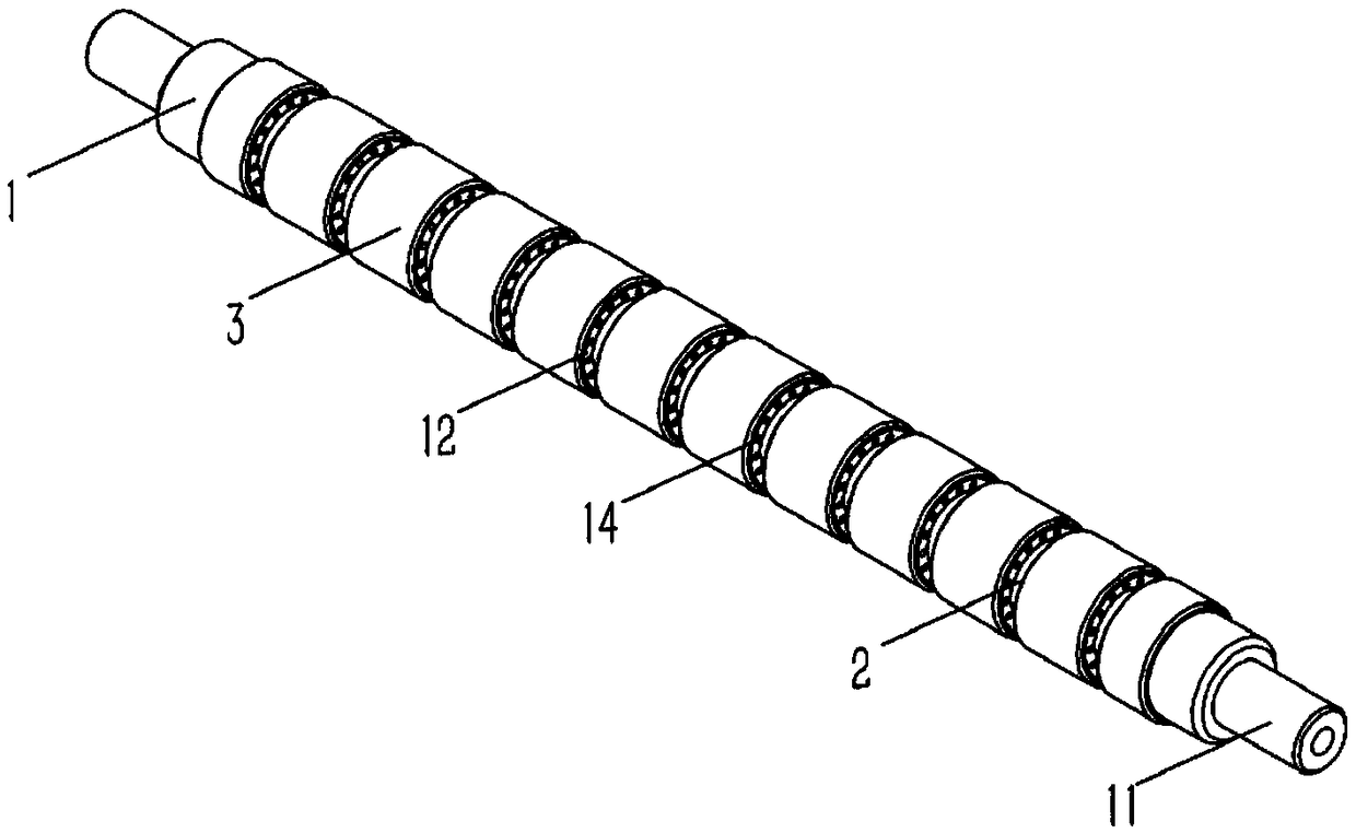
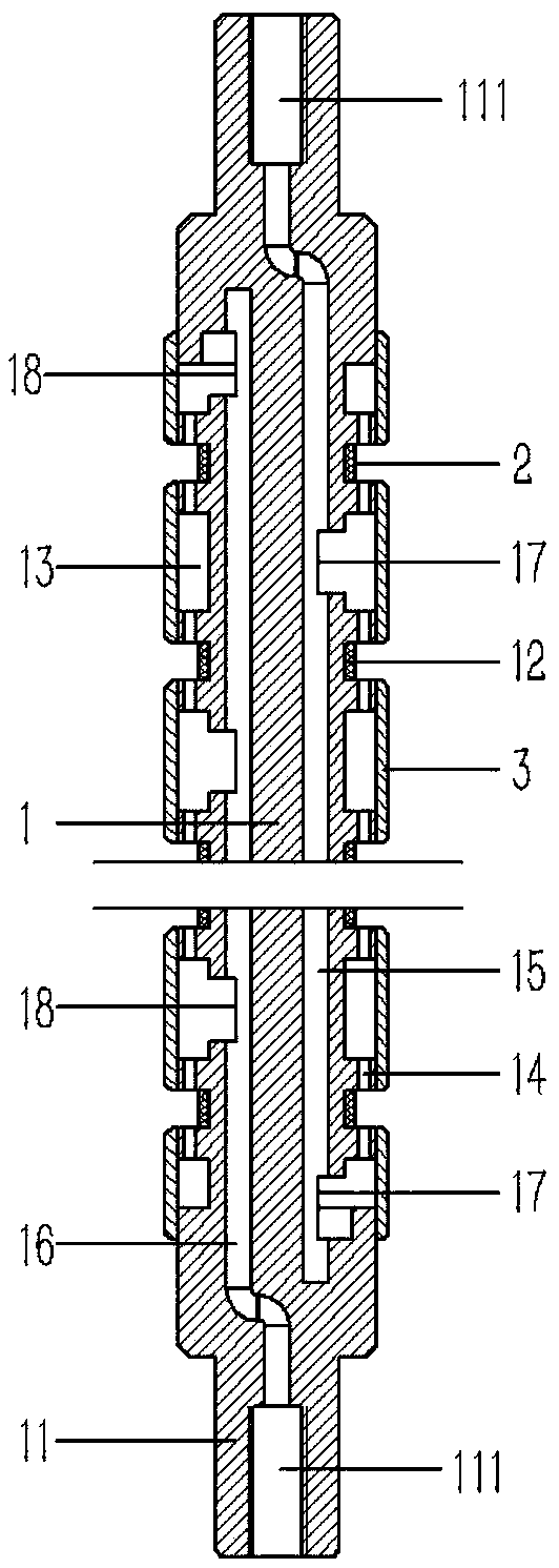
[0015] Example: see figure 1 , 2 As shown, a tape guide roller on a photovoltaic ribbon production equipment includes a roller shaft 1, pillars 11 are formed at both ends of the roller shaft 1, and several annular belt guide grooves 12 are formed on the roller shaft 1, and the roller shaft 1 An annular ventilation groove 13 is formed on the roller shaft 1 between the two ends of the two ends and the adjacent belt guide groove 12, and there are several small holes 14 communicated with the belt guide groove 12 on the side wall of the ventilation groove 13; There are suction channels 15 and blowing channels 16 respectively in the roller shaft 1, and the ventilation slots 13 adjacent to the two sides of the belt guide groove 12 on the roller shaft 1 are respectively formed with suction channels communicating with the suction channels 15 and the blowing channels 16. Air groove holes 17 and blowing groove holes 18; several sealing pipe sleeves 3 covering the ventilation grooves 13 ...


PUM


Abstract

The invention discloses a guide belt roller on photovoltaic welding belt production equipment. Support columns are formed at two ends of a roller shaft of the guide belt roller; multiple annular belt guide grooves are formed in the roller shaft; annular ventilation grooves are formed in two ends of the roller shaft and in the roller shaft between the adjacent belt guide grooves; multiple small holes communicated with the belt guide grooves are formed in the side walls of the ventilation grooves; a wind sucking channel and a wind blowing channel are respectively formed in the roller shaft; wind sucking groove holes and wind blowing groove holes communicated with the wind sucking channel and the wind blowing channel are respectively formed in the ventilation grooves near two sides of the belt guide grooves on the roller shaft; the roller shaft is fixedly sleeved with multiple sealing pipe sleeves for covering the ventilation grooves; thread holes are formed in the support columns at two ends of the roller shaft; and the thread holes at two ends of the roller shaft are respectively communicated with the wind sucking channel and the wind blowing channel in the roller shaft. The structure of the guide belt roller is improved based on a traditional guide belt roller, so that the guide belt roller can achieve the ventilation and the function of drying photovoltaic welding besides of basic functions of a guide belt.

Description

Technical field: [0001] The invention relates to the technical field of photovoltaic product manufacturing equipment, and more specifically relates to a tape guide roller on photovoltaic welding ribbon production equipment. Background technique: [0002] Photovoltaic ribbon, also known as tinned copper ribbon or tin-coated copper ribbon, is mainly used for the connection between photovoltaic module cells, and plays an important role in conducting electricity and gathering electricity. The existing photovoltaic ribbon production method is generally to unwind the copper strip, enter the tin furnace to coat the tin layer, and then clean it, and wind it after cleaning. The production line is generally equipped with a guide roller, and the guide roller is generally It is a roller shaft on which several annular belt guide grooves are formed, and has a single structure and a single function. Invention content: [0003] The purpose of the present invention is to address the defic...

Claims


Application Information

Patent Timeline
Patent Type & Authority Patents(China)
IPC IPC(8): C23C2/00C23C2/08
CPCC23C2/003C23C2/08
Inventor 赵鸿斌
Owner 南京不老村旅游开发有限公司
Learn More