Oil well gas prevention system

An oil well and gas prevention technology, applied in wellbore/well components, production fluid, earthwork drilling and production, etc., can solve the problems that cannot meet the needs of production, the overall structure design is not reasonable, and the liquid carrying capacity is poor, etc. Achieve the effects of avoiding conflicts between layers, improving liquid carrying capacity, and improving liquid production capacity

Inactive Publication Date: 2017-04-19
CHINA PETROLEUM & CHEM CORP
View PDF14 Cites 3 Cited by
  • Summary
  • Abstract
  • Description
  • Claims
  • Application Information

AI Technical Summary

Problems solved by technology

[0002] Currently, CO 2 drive 、 N 2 Gas flooding test, and during the test process, gas channeling usually occurs due to the deep burial of the oil reservoir. In practice, in order to prevent the problem of gas channeling, people have tried many methods, such as the use of hollow anti-air pumps, multi-functional anti-sand oil and gas Separator or even anti-gas technology, hollow air-proof pump and multi-functional oil-gas separator technology can only be applied when the gas-oil ratio is less than 300m 3 For wells / t, although these methods have prevented gas channeling to a certain extent, in the later stage of production, when the gas-oil ratio increases to a certain value, the current gas prevention technology cannot meet the needs of production. In addition, for multi-layer development For the reservoirs, the overall structure design is still not reasonable, and the interlayer interference between the high-pressure layer and the low-pressure layer caused by the permeability difference cannot be avoided. production needs

Method used


Image

  • Oil well gas prevention system
  • Oil well gas prevention system

Examples


Embodiment Construction

[0021] The oil well gas prevention system and usage method of the present invention will be further described in detail below in conjunction with the accompanying drawings and specific implementation methods.

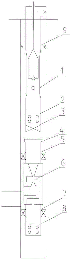
[0022] As shown in the figure, the oil well gas prevention system of the present invention is applied to the occasion where the upper layer is a high pressure gas production layer and the lower layer is a low pressure production layer. The oil pipe is positioned in the oil well casing through the anchor 9, the lower end of the anti-air pump 1 is connected with the upper filter screen 2 and the upper plug 3 in turn, and the oil well casing is also provided with a hand-off joint 4 located below the upper anti-air pump 1, The hand-off joint 4 is positioned in the oil well casing through the upper packer 5 arranged around it, and the lower end of the hand-off joint 4 is connected to an anti-gas lift pump 6, and the anti-gas lift pump 6 is positioned and installed through a l...


PUM


Abstract

The invention discloses an oil well gas prevention system and a using method. The oil well gas prevention system comprises an oil well casing and a gas prevention pump. The lower end of the gas prevention pump 1 is sequentially connected with an upper filter screen pipe and an upper screwed plug. A release sub located below the gas prevention pump 1 is arranged in the oil well casing. The release sub is located in the oil well casing through an upper packer arranged on the periphery of the release sub. The lower end of the release sub is connected with a gas prevention lifting pump. The gas prevention lifting pump is located and installed in the oil well casing through a lower packer. The lower end of the gas prevention lifting pump is connected with a lower filter screen pipe. A lower oil layer liquid inlet is formed below the gas prevention lifting pump. An upper oil layer liquid inlet is formed in one side of the gas prevention lifting pump. The oil well gas prevention system has the following advantages that the production pressure difference of the low-pressure oil layer is increased, the liquid production amoung of the low-pressure layer is increased, interlayer interference is avoided, the function of changing the motion direction of liquid and the acceleration function are achieved, the liquid carrying capacity of gas is improved, and the liquid production capacity of the low-pressure layer is improved; and secondary filter of well liquid is achieved, and a spray nozzle is effectively prevented from being blocked.

Description

technical field [0001] The invention relates to an oil field exploitation equipment, in particular to an oil well gas prevention system and its application method. Background technique [0002] Currently, CO 2 drive 、 N 2 Gas flooding test, and during the test process, gas channeling usually occurs due to the deep burial of the oil reservoir. In practice, in order to prevent the problem of gas channeling, people have tried many methods, such as the use of hollow anti-air pumps, multi-functional anti-sand oil and gas Separator or even anti-gas technology, hollow air-proof pump and multi-functional oil-gas separator technology can only be applied when the gas-oil ratio is less than 300m 3 For wells / t, although these methods have prevented gas channeling to a certain extent, in the later stage of production, when the gas-oil ratio increases to a certain value, the current gas prevention technology cannot meet the needs of production. In addition, for multi-layer development ...

Claims


Application Information

Patent Timeline
Patent Type & Authority Applications(China)
IPC IPC(8): E21B43/14E21B43/12E21B43/32
CPCE21B43/124E21B43/14E21B43/32
Inventor 张宏录张龙胜熊炜赵宇新徐骞王海燕李艺玲黄博张壮李晓雪
Owner CHINA PETROLEUM & CHEM CORP
Why Eureka
Try Eureka