Lamp bracket with light source moving function

A light source and light stand technology, which is applied in the field of light source movable light stand, can solve problems affecting vision and observation, and achieve the effects of centralized lighting, convenient movement, and strong position fixation

Inactive Publication Date: 2017-04-19
SHANGHAI DIANJI UNIV
View PDF7 Cites 3 Cited by
  • Summary
  • Abstract
  • Description
  • Claims
  • Application Information

AI Technical Summary

Problems solved by technology

[0002] Most of the existing lamps are hung in the middle of the roof or on the wall. Because the light source is fixed, they cannot be moved. vision

Method used


Image

  • Lamp bracket with light source moving function
  • Lamp bracket with light source moving function
  • Lamp bracket with light source moving function

Examples


Embodiment Construction

[0020] In order to make the technical means, creative features, goals and effects achieved by the present invention easy to understand, the present invention will be further elaborated below in conjunction with illustrations and specific embodiments.

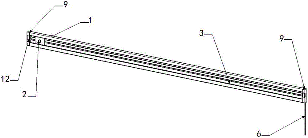
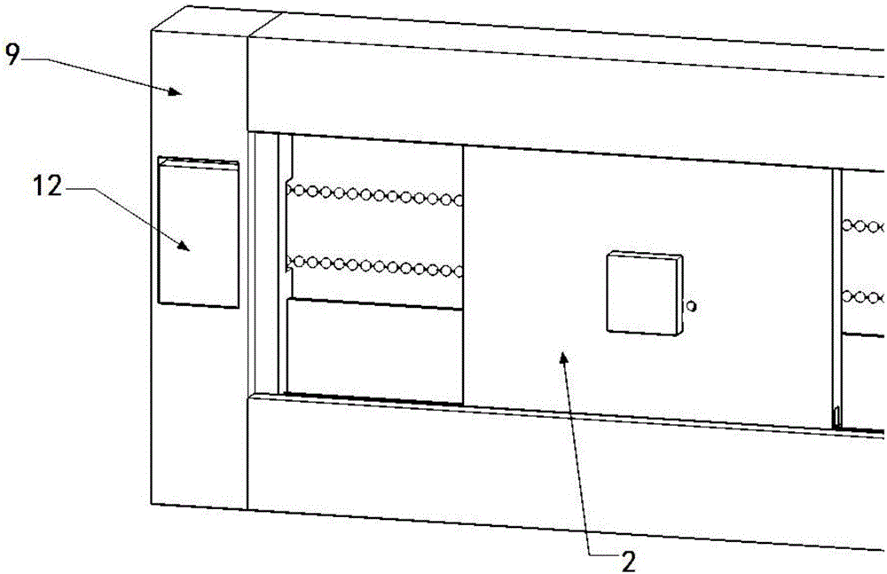
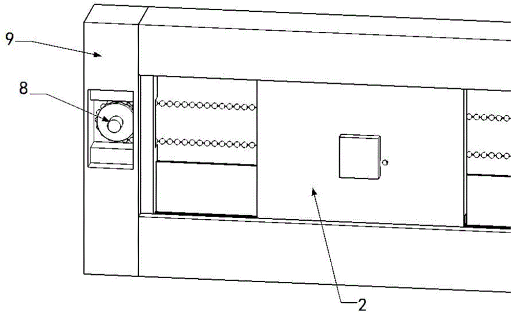
[0021] Such as Figure 1 to Figure 10 As shown, the light source movable lamp stand proposed by the present invention includes a main frame 1 and a lamp holder 2 on which a light source can be installed. There is a movable assembly structure between the lamp holder and the main frame, and the lamp holder is installed on the lamp holder through the movable assembly structure. , and can move on the main frame through the movable assembly structure. The movable assembly structure includes a slide rail 3 located on the side wall of the main frame and a pulley 4 located on the side wall of the lamp holder. The pulley is placed on the slide rail so that the lamp holder can move along the slide rail through the pulley. The slide rail ...


PUM


Abstract

The invention provides a lamp bracket with a light source moving function. The lamp bracket comprises a main bracket body and a lampholder used for installation of a light source. A movable assembling structure is arranged between the lampholder and the main bracket body. The lampholder is installed on the main bracket body through the movable assembling structure and can move on the main bracket body through the movable assembling structure. The movable assembling structure comprises slide rails located on the side wall of the main bracket body and a pulley located on the side wall of the lampholder. The pulley is arranged on the slide rails so that the lampholder can move along the slide rails through the pulley. The slide rails are located on the bottom side of the main bracket body. A limit edge is arranged on the top side of the main bracket body and extends downwards to limit the pulley in the axial direction. The lamp bracket is formed by improving an existing fixed lamp, the structure of the fixed lamp is improved, part of the fixed lamp is changed into a movable bracket, the backlight problem of space illumination is solved, the indoor light source is convenient to move, and the position fixing performance is better; and illumination is concentrated, the vision is not prone to being affected, and the lamp bracket with the light source moving function is suitable for being used by a user with the demand of frequent moving of light sources.

Description

technical field [0001] The invention relates to a lamp, in particular to a movable light stand for a light source. Background technique [0002] Most of the existing lamps are hung in the middle of the roof or on the wall. Because the light source is fixed, they cannot be moved. vision. Therefore, it is necessary to optimize the structure of this lamp to overcome the above-mentioned defects. Contents of the invention [0003] The purpose of the present invention is to provide a light source movable light stand, which solves the limitation of light source fixing, the light source can be fixed in any space conveniently and quickly, has a wide lighting range, and can solve the encountered backlight problem. [0004] The technical scheme that the present invention adopts for solving its technical problem is, [0005] A light source movable lamp stand, including a main frame and a lamp holder on which a light source can be installed, there is a movable assembly structure bet...

Claims


Application Information

Patent Timeline
Patent Type & Authority Applications(China)
IPC IPC(8): F21S8/00F21V21/02F21V17/10F21V21/108F21V14/02
CPCF21S8/00F21V14/02F21V17/10F21V21/02F21V21/108
Inventor 杜浩明曹宇杨陈梦蝶杨洋尹睿奇
Owner SHANGHAI DIANJI UNIV
Why Eureka
Try Eureka