

Output voltage sensor fault diagnosing method of auxiliary current transformer and fault tolerance control method
A technology for assisting converters and sensor faults, applied in the direction of measuring current/voltage, measuring only voltage, instruments, etc., can solve the problems of difficult judgment and low accuracy of fault judgment, achieve low cost, fast and effective fault diagnosis, and improve accuracy Effect
- Summary
- Abstract
- Description
- Claims
- Application Information
AI Technical Summary
Problems solved by technology
Method used
Image

Examples
Embodiment 1
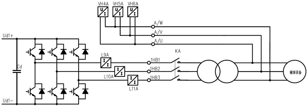
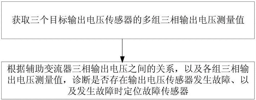
[0048] Such as figure 2 As shown, the method for diagnosing the fault of the output voltage sensor of the auxiliary converter in this embodiment, the steps include:
[0049] 1) Obtain in real time the three-phase output voltage measurement signals of the three target output voltage sensors connected to the locomotive auxiliary converter;
[0050] 2) According to the relationship between the three-phase output voltages of the auxiliary converter and the three-phase output voltage measurement signals obtained in step 1), diagnose whether there is a fault in the output voltage sensor, and locate the faulty sensor when a fault occurs.
[0051] For a three-phase system, the frequency and amplitude of the three line voltages are equal, the phases are different from each other by 120°, and the sum of the instantaneous values of the three line voltages is zero. That is, the frequency and amplitude of the three-phase output voltages of the auxiliary converter in the locomotive are ...
Embodiment 2
[0105]This embodiment is basically the same as Embodiment 1, except that the specific steps for diagnosing whether there is a failure of the output voltage sensor are: calculating the mean value of the sum of the three-phase output voltage measurement values at a specified time, and judging whether it is greater than the preset mean value threshold, If yes, diagnose that there is a faulty output voltage sensor. The average value of the sum of the values of the three-phase output voltage measurement signals is specifically calculated according to formula (1). Based on the characteristic that the sum of the three-phase output voltages of the auxiliary converter is 0, combined with the change characteristics of the average value of the three-phase output voltage under normal and fault conditions, the fault state diagnosis can be realized through the average value exceeding the limit, and the implementation method Simpler than Example 1.
Embodiment 3
[0107] This embodiment is basically the same as Embodiment 1, the difference is that the specific steps for diagnosing whether there is a failure of the output voltage sensor are: calculating the variance between the sum of the three-phase output voltage measurement values at a specified time relative to the nominal mean value, and judging Whether it is greater than the preset variance threshold, and if so, it is diagnosed that there is a failure of the output voltage sensor. The nominal mean value is the mean value of the sum of the three-phase output voltage measurement values under normal working conditions, and the variance is specifically calculated according to formula (2). Based on the characteristics that the sum of the three-phase output voltages of the auxiliary converter is 0, combined with the variation characteristics of the variance of the sum of the three-phase output voltages under normal and fault conditions, the fault state diagnosis can be realized through...
PUM
 Abstract
Description
Claims
Application Information