Light foldable rod antenna for aerospace and preparation method thereof

A folding rod, lightweight technology, applied to folded antennas, antennas suitable for movable objects, flexible antennas, etc., can solve the problems of heavy antenna weight, insufficient extension, and many connection mechanisms, and achieve convenient manufacturing methods. , the effect of simplifying the weight

Inactive Publication Date: 2017-04-19
SHANGHAI COMPOSITES SCI & TECH CO LTD
View PDF4 Cites 3 Cited by
  • Summary
  • Abstract
  • Description
  • Claims
  • Application Information

AI Technical Summary

Problems solved by technology

Since this type of antenna is made of metal material as a whole, there are many connecting mechanisms to control the expansion and contraction, the

Method used


Image

  • Light foldable rod antenna for aerospace and preparation method thereof
  • Light foldable rod antenna for aerospace and preparation method thereof

Examples


Embodiment Construction

[0037] The present invention will be described in detail below in conjunction with specific embodiments. The following examples will help those skilled in the art to further understand the present invention, but do not limit the present invention in any form. It should be noted that those skilled in the art can make several modifications and improvements without departing from the concept of the present invention. These all belong to the protection scope of the present invention.

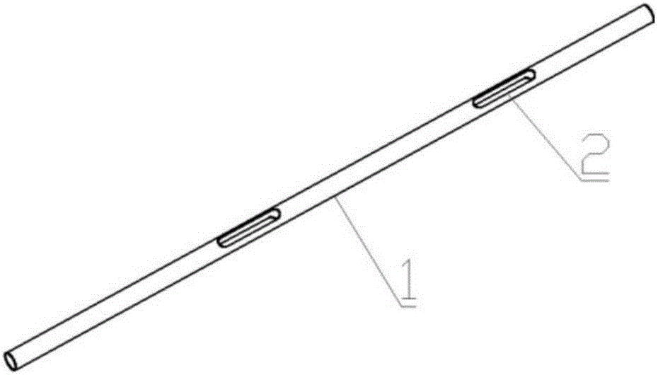
[0038] In this embodiment, the lightweight and foldable rod antenna for spaceflight provided by the present invention includes a rod main body;

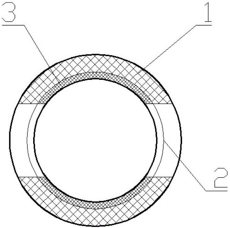
[0039] The bar body includes a support column section 1 and a strain energy hole 2 provided on the support column section 1;

[0040] A conductive layer 3 is provided on the wall surface of the inner hole of the supporting column section 1 .

[0041] The rod body is made of a composite material system; the conductive layer 3 is a metal aluminum layer; ...


PUM


Abstract

The invention provides a light foldable rod antenna for aerospace, which comprises a rod piece main body, and is characterized in that the rod piece main body comprises a supporting column section (1) and strain energy holes (2) arranged in the supporting column section (1); and the inner hole wall of the supporting column section (1) is provided with a conductive layer (3). The rod piece main body is made by adopting a composite material system. The conductive layer (3) is a metal aluminum layer. The composite material system is made by adopting epoxy resin and carbon fibers. The high-performance rod antenna prepared through adopting a light carbon fiber composite material with high performance, adopting a foldable elastic strain energy structure and preparing the metal layer with excellent conductivity at the surface of the composite material can realize automatic unfolding, and substantially simplifies an telescopic control mechanism and reduces the overall weight of the antenna under the premise of maintaining effective receiving and emitting of electric signals.

Description

technical field [0001] The present invention relates to an antenna, in particular to a lightweight foldable rod antenna for aerospace and a preparation method thereof. Background technique [0002] At present, the rod antennas used in the aerospace field are generally made of metal materials in order to realize the transmission of electromagnetic signals. This type of antenna shrinks the antenna to the allowable volume through the mechanism when the spacecraft is launched, and expands it through the stretching mechanism after the spacecraft enters orbit. Since this type of antenna is made of metal material as a whole, there are many connection mechanisms to control the expansion and contraction, the overall weight of the antenna is relatively heavy, and the extension may not be in place during the extension process, and the reliability is low. Contents of the invention [0003] Aiming at the defects in the prior art, the object of the present invention is to provide a lig...

Claims


Application Information

Patent Timeline
IPC IPC(8): H01Q1/08H01Q1/28C08L63/00C08K7/06
CPCH01Q1/085C08K7/06H01Q1/28C08L63/00
Inventor 沈峰梁旭豪史耀辉刘千立刘荣鹏戴晶滨鞠博文陈炳旭田杰
Owner SHANGHAI COMPOSITES SCI & TECH CO LTD
Why Eureka
Try Eureka