
Tissue sealing device with optical feedback

A tissue, optics technique used in the field of surgery

Active Publication Date: 2017-04-19
KONINKLIJKE PHILIPS NV
View PDF6 Cites 0 Cited by
  • Summary
  • Abstract
  • Description
  • Claims
  • Application Information

AI Technical Summary

Problems solved by technology

However, these parameters usually provide only partial information about the tissue, which limits the benefits provided by such feedback

Method used


Image

  • Tissue sealing device with optical feedback
  • Tissue sealing device with optical feedback
  • Tissue sealing device with optical feedback

Examples


Embodiment Construction

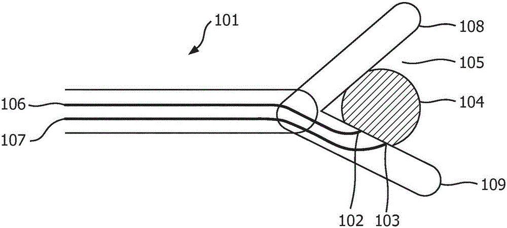
[0022] In order to improve the determination of the state of tissue during a tissue sealing procedure, the present invention is described with respect to forceps or a clamp-type tissue sealing device in which RF energy is used to seal tissue. However, it should be appreciated that the present invention is also applicable to identifying tissue sealing states in tissue sealing devices having other forms of energy delivery and other forms of tissue retention during sealing. The invention also finds application in tissue cutting devices such as electrosurgical scalpels. In such devices, the cutting of tissue by the knife can be used to seal the rest of the tissue; as a result, the invention can be used to monitor the integrity of the resulting seal and provide feedback to the cutting process to optimize the seal. The method of the invention is generally also applied to surgical probes; for example, the determination of the state of tissue sealing after a tissue sealing procedure h...


PUM


Abstract

The present invention relates to a method for determining a state of tissue sealing during a tissue sealing process. According to the disclosed method, an optical probe beam is used to irradiate a tissue region. A signal indicative of optical scattering in the tissue region is generated from a portion of the optical probe beam that has passed through or been returned by the tissue region. The onset of tissue sealing is indicated by the successive occurrence in time of a turning point and a point of inflection in the optical scattering signal. An energy-based tissue sealing or tissue-cutting device for use in accordance with the method is also disclosed.

Description

technical field [0001] The invention relates to a method for indicating the state of tissue closure and has particular application in the field of surgery. The method can be used in conjunction with energy-based tissue sealing or tissue cutting devices. Background technique [0002] In surgery, energy-based tissue sealing devices are used in procedures such as laparoscopy to hemostatically seal blood vessels and arteries. Such devices, also known as tissue-adhesive or tissue-welding devices, apply heat to areas of tissue in order to induce tissue transformations such as denaturation of proteins, dehydration of the tissue and alter collagen bonds. Usually obtained by e.g. in such as Ligasure sold by Covidien TM Tissue-contacting electrodes in the clamping device deliver energy to the tissue region in the form of radio frequency (RF), or high-frequency RF. Other devices are contemplated to deliver energy to tissue regions in the form of optical or thermal energy. After an ...

Claims


Application Information

Patent Timeline
Patent Type & Authority Applications(China)
IPC IPC(8): A61B18/04A61B5/00G01N21/47
CPCA61B5/0084A61B18/04G01N21/47A61B2018/00702A61B2018/00678A61B2018/0063A61B2018/00642A61B18/1442A61B2017/00057A61B2017/00061A61B5/0075A61B18/203A61B18/22A61B18/24A61B2018/1455A61B2018/2261
Inventor B·H·W·亨德里克斯T·M·比德隆V·V·普利C·F·希欧S·M·范登博斯G·W·吕卡森
Owner KONINKLIJKE PHILIPS NV
Learn More