Dirty oil water separator with built-in flow restraining device

A technology for separating equipment and sewage oil and water, which is applied in the direction of liquid separation, separation method, grease/oily substance/floating matter removal device, etc. It can solve the problems of turbulent flow direction, unfavorable filter element, and low processing efficiency, so as to promote floating and reduce Filtration load, effect of improving separation effect and separation efficiency

Active Publication Date: 2017-04-26
安徽百川源新型材料科技有限公司
View PDF5 Cites 2 Cited by
  • Summary
  • Abstract
  • Description
  • Claims
  • Application Information

AI Technical Summary

Problems solved by technology

Therefore, ships and catering industries are equipped with sewage oil-water separation devices, but many problems are still exposed in the process of use: on the one hand, the sewage oil-water separation devices perform oil-water separation treatment on the sewage oil and water to be treated under normal pressure, and the separation effect is not good. On the other hand, when the sewage oil and water to be treated flow to the filter element, the flow direction is disordered, which is not conducive to the timely floating of the oil collected on the filter element; therefore, the separation effect of oil and water is not good, and often requires multiple cycles of treatment, and the treatment efficiency is low

Method used


Image

  • Dirty oil water separator with built-in flow restraining device
  • Dirty oil water separator with built-in flow restraining device
  • Dirty oil water separator with built-in flow restraining device

Examples


Embodiment Construction

[0030] In order to clarify the technical scheme and technical purpose of the present invention, the present invention will be further introduced below in conjunction with the accompanying drawings and specific implementation methods.

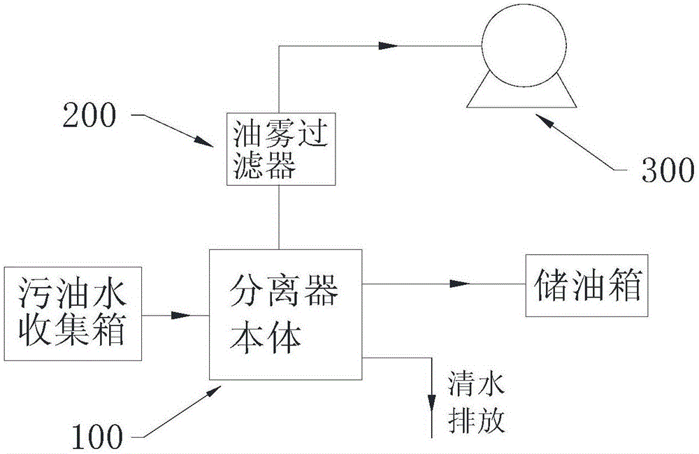
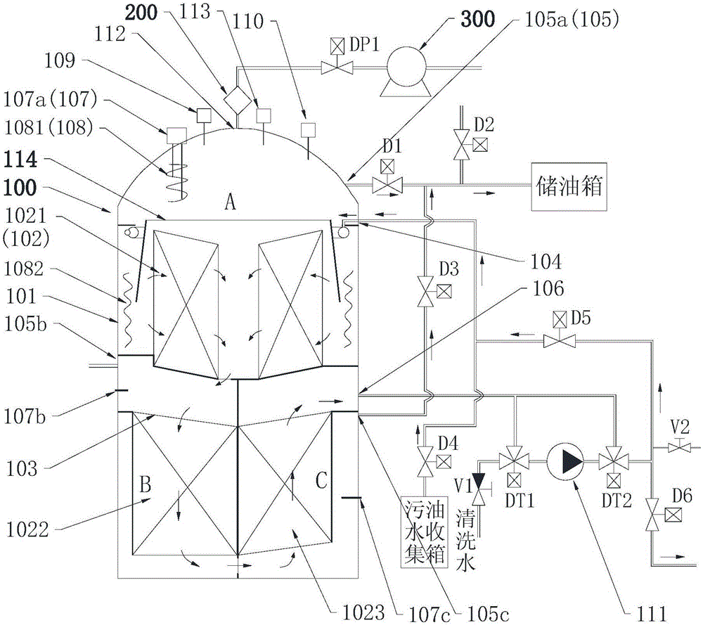
[0031] A kind of sewage oil-water separation equipment with built-in beam device of the present invention, such as Figure 1-Figure 2 As shown, the separation device includes a separator body 100, an oil mist filter 200, a vacuum pump 300, an oil storage tank, a dirty oil water collection tank and a control unit. The control part is used to automatically control the waste oil-water separation equipment of the present invention. The top of the shell 101 of the separator body 100 is provided with an air suction port 112 and an input port 104 for inputting sewage oil and water to be treated. The output port of the dirty oil and water collection tank communicates with the input port 104, the input port of the oil mist filter 200 communicates with t...


PUM


Abstract

The invention discloses a dirty oil water separator with a built-in flow restraining device; the dirty oil water separator comprises a separator body, the flow restraining device and a vacuum pump. The separator body is provided with an extraction port communicating with the vacuum pump and an input port for influx of dirty oil water, and the separator body is internally provided with a cylindrical first filter core arranged vertically and used for coarse filtration. The flow restraining device comprises an input part and at least two flow restraining parts which are connected with each other, the flow restraining parts are used for restraining the flowing-out direction of the dirty oil water, and output ports of the flow restraining parts are distributed along the consistent angle direction. The flow restraining device is assembled on the top side of the first filter core, and the output ports of the flow restraining parts are located between the first filter core and a shell body of the separator body. The flow restraining device is used for retaining the flow direction of the dirty oil water flowing to the first filter core, is used for oil and water pre-separation treatment of the dirty oil water and is used for timely removing dirty oil droplets gathered on the first filter core, so the filtration load of the filter core is reduced, oil-water separation is performed in vacuum conditions, and the separation effect and the separation efficiency of the separator are facilitated to be improved.

Description

technical field [0001] The invention relates to a sewage oil-water separation device, in particular to a sewage oil-water separation device with a built-in beam device that restricts the flow direction of the sewage oil and water to be treated and separates oil and water under vacuum conditions, and belongs to the field of sewage treatment. Background technique [0002] With the rapid development of society and the substantial improvement of people's quality of life, people produce a large amount of oily sewage in their daily life activities, such as domestic sewage produced in daily life activities, especially a large amount of catering sewage produced by the catering industry; The ship sewage produced by the ships that people travel and play contains a large amount of dirty oil. Direct discharge of oily sewage will inevitably cause pollution to rivers or the sea, affecting the normal growth of river organisms or marine organisms. The country and the International Maritime...

Claims


Application Information

Patent Timeline
Patent Type & Authority Applications(China)
IPC IPC(8): B01D17/022B01D17/028B01D17/038C02F1/40
Inventor 陈鸽
Owner 安徽百川源新型材料科技有限公司
Why Eureka
Try Eureka