
CNC cutting tool and CNC machining method

A processing method and tool technology, applied in the field of mechanical processing, to achieve the effect of fast processing speed, not easy to break the tool, and long tool life

Inactive Publication Date: 2017-04-26
GUANGDONG EVERWIN PRECISION TECH
View PDF8 Cites 2 Cited by
  • Summary
  • Abstract
  • Description
  • Claims
  • Application Information

AI Technical Summary

Problems solved by technology

[0003] The main purpose of the present invention is to propose a CNC cutting tool and CNC machining method, aiming to solve the machining of product apertures with small R angles

Method used


Image

  • CNC cutting tool and CNC machining method
  • CNC cutting tool and CNC machining method
  • CNC cutting tool and CNC machining method

Examples


Embodiment Construction

[0025] The technical solutions in the embodiments of the present invention will be clearly and completely described below in conjunction with the accompanying drawings. Apparently, the described embodiments are only part of the embodiments of the present invention, not all of them. Based on the embodiments of the present invention, all other embodiments obtained by persons of ordinary skill in the art without creative efforts fall within the protection scope of the present invention.

[0026] It should be noted that if there are directional indications (such as up, down, left, right, front, back...) in the embodiment of the present invention, the directional indications are only used to explain how to move in a certain posture (as shown in the accompanying drawings). If the specific posture changes, the directional indication will also change accordingly.

[0027] Such as Figure 4-Figure 6 As shown, the CNC tool of the present invention includes an integrally formed body 2 a...


PUM

PropertyMeasurementUnit
Thicknessaaaaaaaaaa

Abstract

The invention discloses a CNC cutting tool. The CNC cutting tool comprises an integrated body and a cutting edge. One end of the body is the fixing end of the cutting tool, and the other end of the body is the cutting end; and the outer contour of the cutting end is the same with the contour of a to-be-machined aperture, the cutting edge is the last edge of the cutting end, and the end face of the cutting end is an internal concave hook face. According to the CNC cutting tool, the invention further provides a CNC machining method. The CNC machining method comprises the following steps that (1), through a common drill or a milling cutter, a to-be-machined part is subjected to rough treatment; (2), main shaft rotation is stopped, the CNC cutting tool is switched, and the orientation of the CNC cutting tool is positioned; (3), the cutting tool falls quickly to conduct punching; and (4), the cutting tool is raised up, and machining is finished. According to the CNC cutting tool and CNC machining method, tool breaking is not prone to happening, so that a defective product owing to tool breaking is not produced, the machining speed is quick, and the service life of the cutting tool is long.

Description

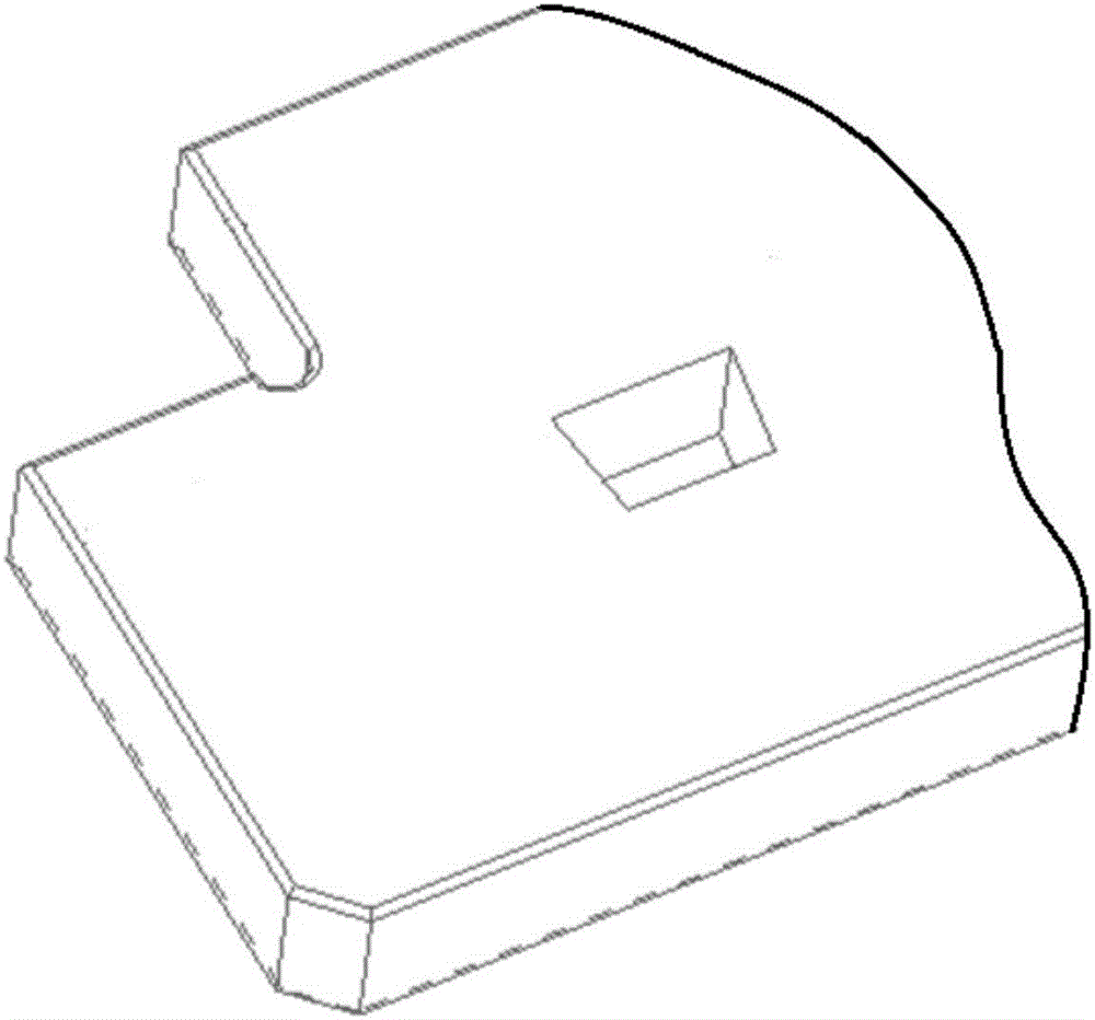
technical field [0001] The invention relates to the field of machining, in particular to small-sized R-angle and right-angle CNC machining tools and a CNC machining method. Background technique [0002] The processing of ordinary hole structures, because they are all processed by high-speed rotating tools, generally cannot process such figure 1 The sharp corner hole structure of the square hole shown is also difficult to process such as figure 2 and image 3 The small size R corner hole shown (generally refers to R≤0.3mm). Contents of the invention [0003] The main purpose of the present invention is to propose a kind of CNC cutting tool and CNC machining method, aiming at solving the machining of the product aperture with small size R angle. [0004] In order to achieve the above object, the present invention proposes a CNC tool, which includes an integrally formed body and a cutting edge, one end of the body is the fixed end of the tool, and the other end is the cut...

Claims


Application Information

Patent Timeline
IPC IPC(8): B21D28/34B23P15/00
CPCB21D28/34B23P15/00
Inventor 张锐
Owner GUANGDONG EVERWIN PRECISION TECH
Learn More