Skipping line-rolling device

A jumping and rolling line technology, which is applied in printing, rotary printing machines, printing machines, etc., can solve the problems of short service life of the blade, inability to cut the edge of the paper, and easy chipping of the blade, and achieve simple and compact structure, low cost, The effect of long wear life

Inactive Publication Date: 2009-08-26
SHANGHAI XINMIN TAIYO KIKAI
View PDF5 Cites 0 Cited by
  • Summary
  • Abstract
  • Description
  • Claims
  • Application Information

AI Technical Summary

Problems solved by technology

[0002] In the post-press collating machine of a large printing machine, the upper paper and the bottom paper need to be glued together on all four sides, while the middle paper only needs to be glued to one side, and the middle paper except for the pasted side, the other three sides are smaller than the upper paper and the lower paper , so in the continuous collation, it is necessary to die-cut the edge of the folder. The die-cutting form is two horizontal rolling and one longitudinal rolling die-cutting the next edge. The wear resistance puts forward very high requirements. The general design uses a round anvil cylinder and only a small piece of blade is fixed on the knife cylinder. The blade is easily broken due to impact, and the service life of the blade is short. The general structure design is in the case of blade wear. It is prone to incomplete slitting and cannot cut the paper edge. At this time, it can only be shut down for debugging, which reduces the efficiency

Method used


Image

  • Skipping line-rolling device
  • Skipping line-rolling device

Examples


Embodiment

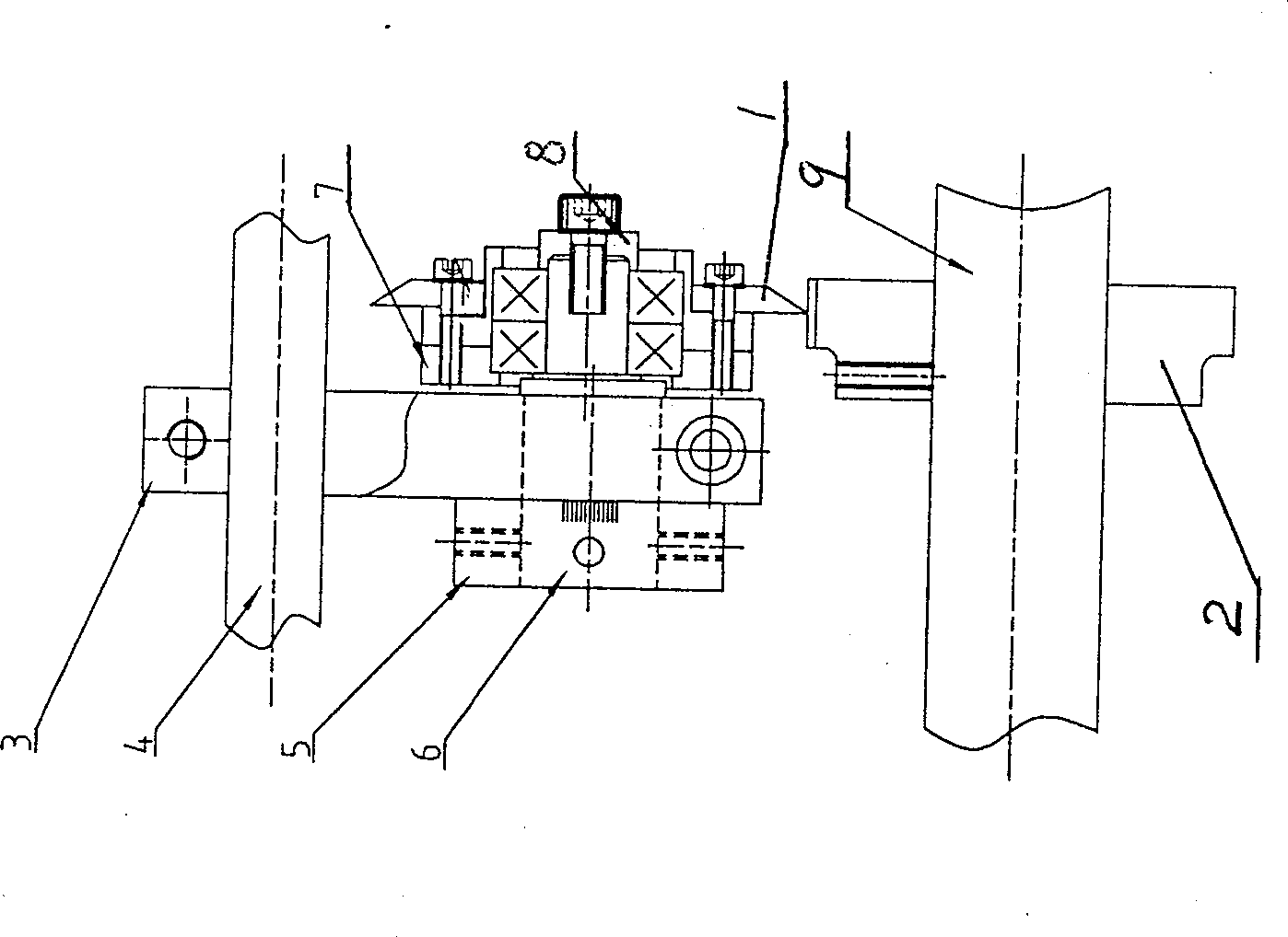
[0011] like figure 1 As shown, it is a structural schematic diagram of a jump-type rolling device, which is composed of a blade 1, a cam anvil 2, a connecting block 3, a fixed shaft 4, a positioning cap 5, an eccentric knife shaft 6, Bearing 7, gland 8 and anvil shaft 9 are composed.

[0012] First put the fixed shaft 4 through the connecting block 3 and then lock it with screws, then put the eccentric knife shaft 6 into the hole on the connecting block 3, fix it with the positioning cap 5 and pass it through the connecting pin and tighten it with the top screw. A bearing 7 is installed at the other end, the blade 1 is a round blade, which is fastened to the bearing 7 by screws, the gland 8 is fixed to the center of the blade 1 by screws, and the cam anvil 2 is set directly under the blade 1, and the anvil shaft 9 passes through cam anvil 2, and fix the cam anvil 2 with the top screw.

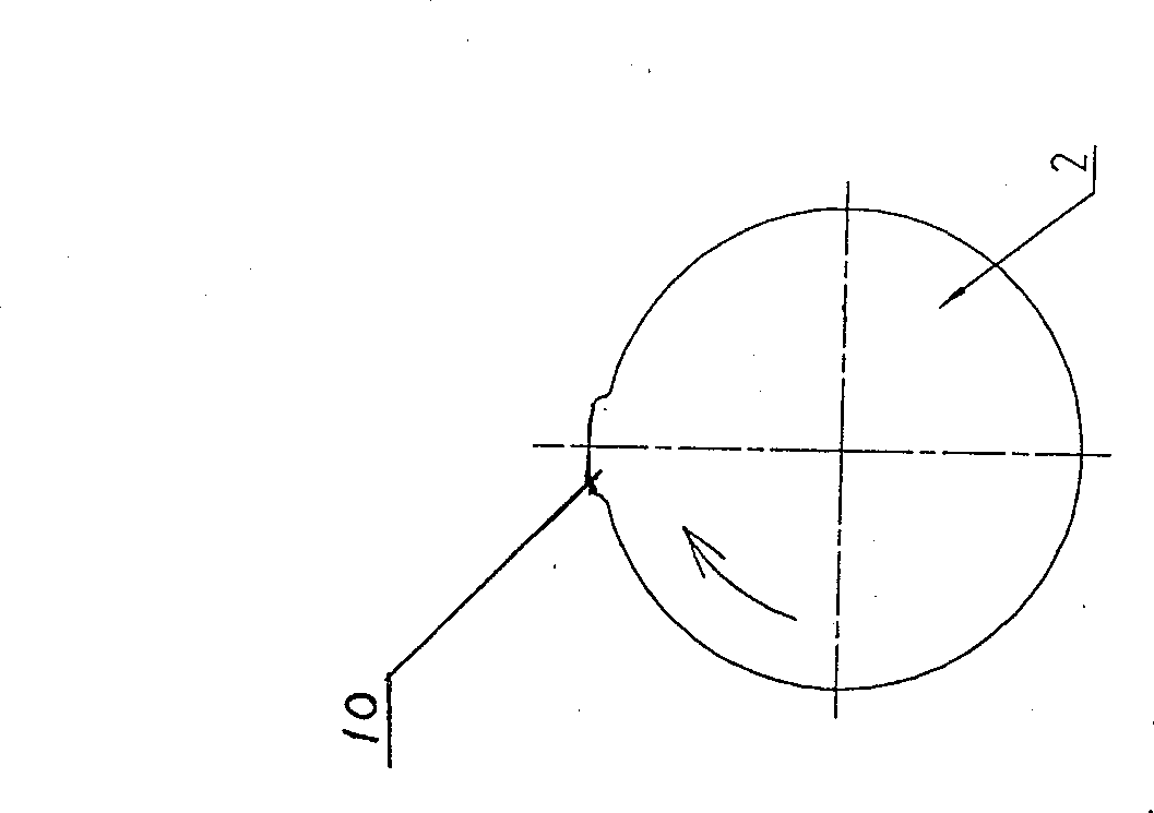
[0013] like figure 2 As shown, it is a schematic diagram of the structure of the cam an...


PUM


Abstract

The jumping thread cutting device consists of a cutting blade screwed to a bearing, a cam anvil tube below the fixed blade, a connecting block, a fixing shaft over the connecting block, a locating cap, an eccentric cutter shaft inside the hole in the lower part of the connecting block and with one end fixed by the locating cap and the other end with bearing, a bearing, a gland for fixing the center of the cutting blade, and an anvil tube shaft penetrating the cam anvil tube to fix it. The present invention has the advantages of compact structure, high reliability, low cost, high longitudinal cutting precision and capacity of regulating the pressure to the longitudinal cutter during operation.

Description

technical field [0001] The invention relates to a jump-type rolling line device, which is used for a collating machine behind a printing press, and belongs to the technical field of printing machinery. Background technique [0002] In the post-press collating machine of a large-scale printing machine, the upper paper and the bottom paper need to be pasted together on all four sides, and only one side of the middle page needs to be glued together, and the other three sides of the middle page except the pasted edge are smaller than the upper and lower paper. Therefore, in the continuous collation, the die-cutting edge of the interleaf should be carried out. The die-cutting form is two horizontal rolling and one longitudinal rolling die-cutting edge. Because the longitudinal cutting marks are small, the impact resistance of the blade and the Wear resistance puts forward high requirements. Generally, a circular anvil cylinder is used in the general design and only a small blade ...

Claims


Application Information

Patent Timeline
Patent Type & Authority Patents(China)
IPC IPC(8): B41F13/56B41F13/64
Inventor 祁和亮杨泽
Owner SHANGHAI XINMIN TAIYO KIKAI
Why Eureka
Try Eureka