
Heat pipe groove forming tool and method for 5G base station equipment shell

A technology of base station equipment and forming knives, which is applied in the direction of milling machine equipment, milling machine equipment details, metal processing equipment, etc., can solve the problems of difficult to guarantee product quality, affect the heat dissipation effect of equipment, and different sizes of heat pipe grooves, so as to achieve the goal of not being easy to wear and tear The effect of breaking the knife and strong versatility

Active Publication Date: 2020-09-25
ZHUHAI RUNXINGTAI ELECTRICAL
View PDF6 Cites 0 Cited by
  • Summary
  • Abstract
  • Description
  • Claims
  • Application Information

AI Technical Summary

Problems solved by technology

The existing heat pipe groove opening method is to rough-mill the rough outline of the heat pipe groove first, and then fine-mill the predetermined cross-sectional shape. The fine-milling process requires the machining center to control the milling cutter to move up and down, left, and right in the heat pipe groove repeatedly, which requires multiple times. Milling forming, low efficiency
The cross-sectional shape of the heat pipe groove is determined by the shape and direction of the milling cutter. The heat pipe grooves processed by different manufacturers have different sizes, and the product quality is difficult to guarantee.
Heat pipe slots of different sizes and shapes are likely to cause cracks in the assembled copper pipes, affecting the heat dissipation effect of the equipment

Method used


Image

  • Heat pipe groove forming tool and method for 5G base station equipment shell
  • Heat pipe groove forming tool and method for 5G base station equipment shell
  • Heat pipe groove forming tool and method for 5G base station equipment shell

Examples


Embodiment Construction

[0024] In order to make the object, technical solution and advantages of the present invention clearer, the present invention will be further described in detail below in conjunction with the accompanying drawings. It is only stated here that the words for directions such as up, down, left, right, front, back, inside, and outside that appear or will appear in the text of the present invention are only based on the accompanying drawings of the present invention, and are not specific to the present invention. limited.

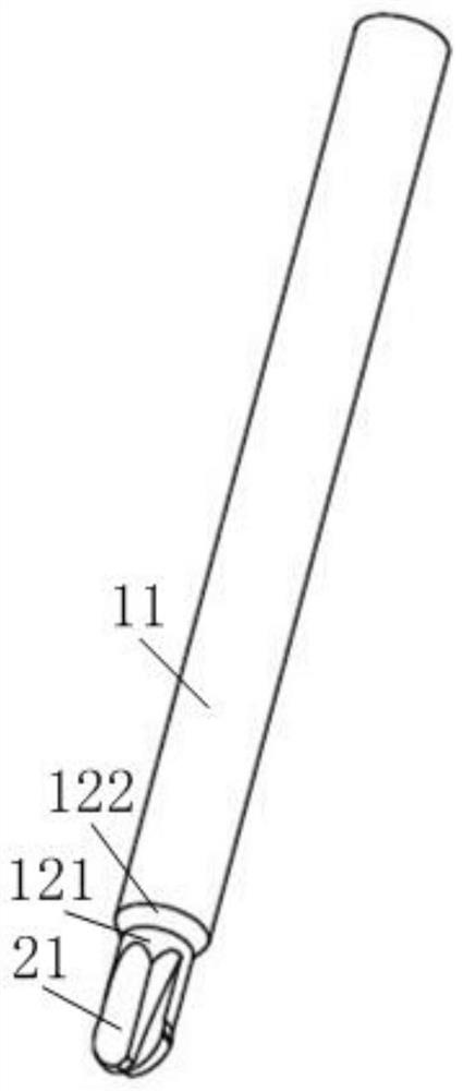
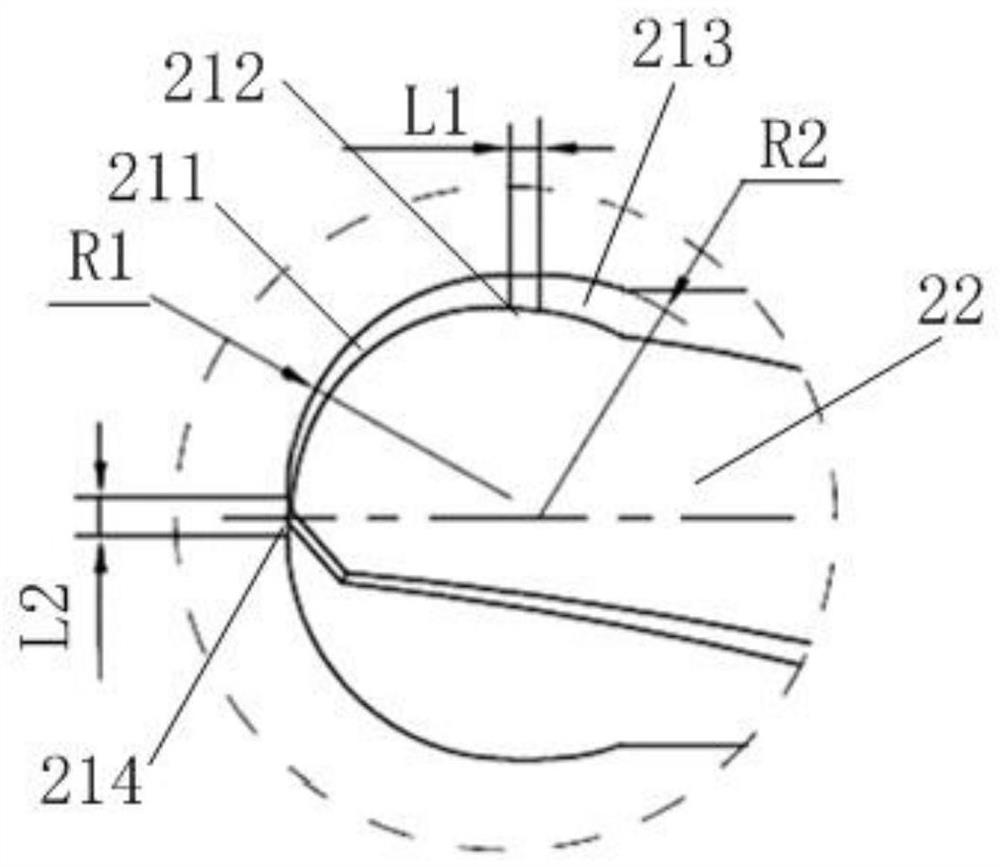
[0025] Such as Figure 1-Figure 4 As shown, the first embodiment of the present invention provides a heat pipe groove forming knife for a 5G base station equipment housing, including an integrally formed knife handle 1 and a cutting part 2; the knife handle 1 and the cutting part 2 have the same central axis The cutting part 2 includes a cutting edge 21 and a chip flute 22; the cutting edge 21 includes a lower arc cutting edge 211, a straight cutting edge 212 an...


PUM


Abstract

The embodiment of the invention discloses a heat pipe groove forming tool for a 5G base station equipment shell. The forming tool comprises a tool handle and a cutting portion which are integrally formed. The tool handle and the cutting portion have the same center axis. The cutting portion comprises a cutting blade and a chip groove. The cutting blade comprises a lower arc cutting blade, a linearcutting blade and an upper arc cutting blade which are sequentially connected from bottom to top. The tool handle comprises a tool handle body and a connecting transition portion. The cutting portionis connected with the tool handle body through the connecting transition portion. The embodiment of the invention further discloses a heat pipe groove forming method for the 5G base station equipmentshell. By adopting the forming method, it can be ensured that when the forming tool rotates, the cutting surface keeps line contact with materials, abrasion is not likely to be caused, and the service life of the tool is prolonged. The tool handle body and the cutting portion are connected firmly, and the tool is not likely to be broken. In the milling process, the cutting portion can stretch into materials to be machined through the transition portion, the forming technology for heat pipe grooves of different depths can be achieved, and the universality is high.

Description

technical field [0001] The invention relates to the production field of 5G base station equipment shells, in particular to a heat pipe groove forming knife and a forming method for a 5G base station equipment shell. Background technique [0002] 5G base station equipment generates a lot of heat. It is often necessary to install heat pipe grooves on the housing, install heat pipes in the heat pipe grooves, and collect heat from around the housing through the heat pipes and transfer them to the radiator for heat dissipation. Through the above method, it can be ensured that the heat generated by the 5G base station equipment can be discharged in time to ensure the stability of its internal components. [0003] Since the heat pipe groove must be designed with its own specific shape so that the heat pipe can be fixed in the groove, the cross section of the heat pipe groove is mostly arc-shaped with an apex angle greater than 180 degrees. The existing heat pipe groove opening met...

Claims


Application Information

Patent Timeline
Patent Type & Authority Applications(China)
IPC IPC(8): B23C3/28B23C5/10B23C5/12
CPCB23C5/10B23C5/12B23C3/28
Inventor 张莹梁绍钜蓝志平陈钦义任怀德
Owner ZHUHAI RUNXINGTAI ELECTRICAL
Learn More