
Method for compensating transmission chain errors of aircraft model of decoupling mechanism in captive trajectory tests

A technology of error compensation and transmission chain, which is applied in the field of error compensation of the aircraft model transmission chain of decoupling mechanism in the capture trajectory test, and can solve the problem of trajectory error of the degree of freedom movement

Active Publication Date: 2017-04-26
CHONGQING UNIV +1
View PDF10 Cites 13 Cited by
  • Summary
  • Abstract
  • Description
  • Claims
  • Application Information

AI Technical Summary

Problems solved by technology

It can be understood that the six degrees of freedom include: three-degree-of-freedom motion displacement axial X, normal Y, lateral Z and three-degree-of-freedom motion angle pitch angle α, yaw angle β and roll angle γ, due to mechanism processing, There are errors in the installation and transmission parts, so there is a certain error in the trajectory of each degree of freedom at the end of the mechanism

Method used


Image

  • Method for compensating transmission chain errors of aircraft model of decoupling mechanism in captive trajectory tests
  • Method for compensating transmission chain errors of aircraft model of decoupling mechanism in captive trajectory tests
  • Method for compensating transmission chain errors of aircraft model of decoupling mechanism in captive trajectory tests

Examples


Embodiment Construction

[0024] The following description serves to disclose the present invention to enable those skilled in the art to carry out the present invention. The preferred embodiments described below are only examples, and those skilled in the art can devise other obvious variations. The basic principles of the present invention defined in the following description can be applied to other embodiments, variations, improvements, equivalents and other technical solutions without departing from the spirit and scope of the present invention.

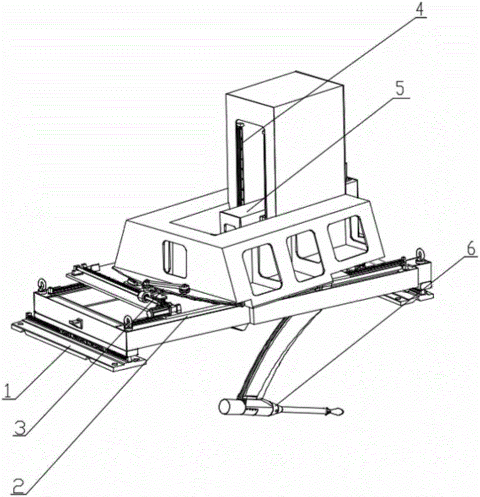
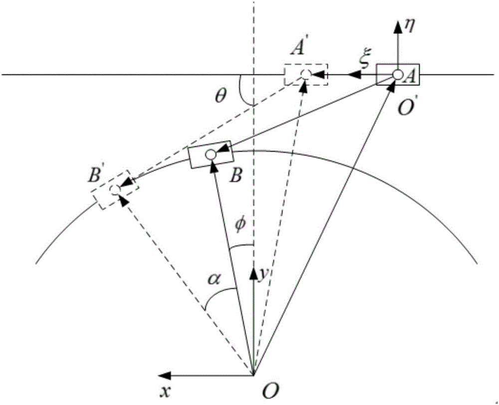
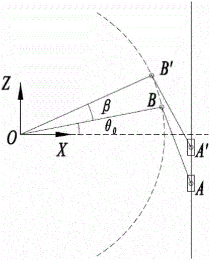
[0025] Such as Figure 1 to Figure 4 , a six-degree-of-freedom mechanism decoupling mechanism used in the capture trajectory test, wherein the six-degree-of-freedom mechanism includes a Z-direction motion mechanism 1, an X-direction motion mechanism 2, a yaw-beta motion mechanism 3, and a Y-direction motion mechanism Mechanism 4, a pitching α motion mechanism 5 and a rolling γ motion mechanism 6, wherein the Z-direction motion mechanism 1, the X-directio...


PUM


Abstract

The invention provides a method for compensating transmission chain errors of an aircraft model of a decoupling mechanism in captive trajectory tests. The method comprises the steps that mechanism kinematic positive solution analysis is conducted to determine a theoretical relation matrix between tail end poses of the decoupling mechanism and motor rotating angles; actual joint parameters of the decoupling mechanism are determined through a portable measuring arm and compared with theoretical values to obtain joint parameter errors of all freedom degrees; a corresponding relation table between expected tail end poses and the actual transmission chain pose errors is established; a motor angle compensation table corresponding to the transmission chain pose errors is established; and a pose error is found out by checking the relation table between the expected tail end poses and the actual transmission chain pose errors according to a given expected pose, and further a motor angle compensation amount is found out by checking the motor angle compensation table corresponding to the transmission chain pose errors, and a motor input angle is adjusted to achieve the purpose of error compensation so as to ensure the precision of the decoupling mechanism participating in the captive trajectory tests. By adoption of the method, the precision of the six-freedom-degree mechanism participating in the captive trajectory tests is ensured, and errors of detached body mechanisms in all freedom degree transmission parts can be accurately compensated.

Description

technical field [0001] The invention relates to an error compensation method for a multi-body separation mechanism system in a wind tunnel test, belonging to the field of precision technology, in particular to an error compensation method for an aircraft model transmission chain of a decoupling mechanism in a capture track test. Background technique [0002] To carry out the multi-body separation test in the wind tunnel, a set of separation body model mechanism installed inside the wind tunnel and controlled by the computer is required to support the separation body test model and provide six degrees of freedom (axial X, normal Y, lateral Z, pitch angle α, yaw angle β and roll angle γ) motion function. [0003] In order to meet the requirements of the multi-body separation test, the separation body model mechanism needs to have a large range of motion, high bearing capacity and motion accuracy, and can reach the designated position at the fastest speed. anywhere. In order ...

Claims


Application Information

Patent Timeline
IPC IPC(8): B25J9/16
CPCB25J9/1607B25J9/1633B25J9/1638B25J9/1692
Inventor 陈超倪卫郑万国宋代平范乃吉谢志江周扬张尽力朱小龙李亮亮袁晓东
Owner CHONGQING UNIV
Learn More