Carbon fiber electric heating tile slotting equipment

A carbon fiber and ceramic tile technology, applied in grinding/polishing equipment, stone processing equipment, metal processing equipment, etc., can solve problems such as slotting at the bottom of tiles, and achieve the effect of preventing high temperature cracking

Active Publication Date: 2017-04-26
保定市华宁电热科技有限公司
View PDF8 Cites 0 Cited by
  • Summary
  • Abstract
  • Description
  • Claims
  • Application Information

AI Technical Summary

Problems solved by technology

But there is currently no equipment for slotting the bottom of the tiles

Method used


Image

  • Carbon fiber electric heating tile slotting equipment
  • Carbon fiber electric heating tile slotting equipment
  • Carbon fiber electric heating tile slotting equipment

Examples


Embodiment Construction

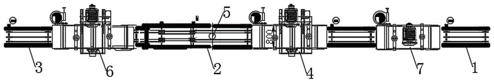
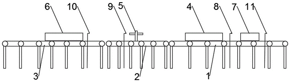
[0030] like Figure 1-6 As shown, a carbon fiber electrothermal tile throwing device includes a feeding conveying device 1, a first throwing device 4, an intermediate conveying device 2, a rotating device 5, a discharging conveying device 3 and a second throwing device 6;

[0031] The first trough throwing device 4 is arranged on the feeding conveying device 1, and is used for the first trough throwing of the tiles;

[0032] The rotating device 5 is a sucker-type rotating device, which is used to rotate the tiles after the first groove throwing by 180°;

[0033] The second groove throwing device 6 is arranged on the discharge conveying device 3, and is used to throw the tiles for the second time;

[0034] Both the first throwing tank and the second throwing tank are carried out in a water environment, and the whole set of equipment is located in a pool, and the bottom of the pool is connected to a secondary pool through a filter port, so as to recycle water resources;

[003...


PUM


Abstract

The invention discloses carbon fiber electric heating tile slotting equipment which comprises a feeding and transferring device, a first slotting device, a middle transferring device, a rotating device, a discharging and transferring device and a second slotting device. The first slotting device is arranged on the feeding and transferring device and used for conducting primary slotting on tiles. The rotating device is a suction disc type rotating device and is used for rotating the tiles subjected to primary slotting by 180 degrees. The second slotting device is arranged on the discharging and transferring device and used for conducting secondary slotting on the tiles. Primary slotting and secondary slotting are both conducted in a water environment. The feeding and transferring device, the first slotting device, the middle transferring device, the rotating device, the discharging and transferring device and the second slotting device are all controlled by a controller. By adoption of the carbon fiber electric heating tile slotting equipment, the purpose of efficient and rapid slotting at the bottoms of the tiles is achieved.

Description

technical field [0001] The invention relates to a carbon fiber electric heating ceramic tile groove throwing device. Background technique [0002] Most of the current electric heating tiles have a layered structure, and heating wires are arranged at the bottom of this shape as an electric heating layer. This method has low thermal efficiency and affects the heat dissipation effect. According to actual needs, a tile with a groove at the bottom has been developed, and the carbon fiber heating wire is evenly arranged in the groove of the tile, which greatly improves the heat dissipation efficiency. But currently there is no equipment for slotting the bottom of the tiles. Contents of the invention [0003] In order to solve the above-mentioned technical problems, the object of the present invention is to provide a carbon fiber electric heating ceramic tile groove throwing equipment. [0004] For reaching above-mentioned object, the present invention adopts following technic...

Claims


Application Information

Patent Timeline
IPC IPC(8): B28D1/04B28D7/00B24B7/22
CPCB24B7/22B28D1/048B28D7/00
Inventor 徐慧忠
Owner 保定市华宁电热科技有限公司
Why Eureka
Try Eureka