Injection mold and machining and assembling technology

A technology for injection molds and injection molded parts, which is applied in the field of injection molds, processing and assembly technology, and can solve the problems of low frame opening precision of board A and board B, lack of positioning function, deviation of internal mold reference plane, etc., so as to avoid duplication Processing and internal mold scrapping risks, improving processing methods and techniques, and ensuring the effect of zero error in processing

Inactive Publication Date: 2017-04-26
FOSHAN CITY SHUNDE DISTRICT BAINIAN TECH CO LTD
View PDF4 Cites 2 Cited by
  • Summary
  • Abstract
  • Description
  • Claims
  • Application Information

AI Technical Summary

Problems solved by technology

Analyzing the reasons, there are mainly four aspects: 1. The frame opening accuracy of the A-plate and B-plate of the mold is not high, and deviations are easy to occur
2. Deviation of the reference plane of the internal mold, damage or secondary processing, resulting in non-coplanar reference of the front and rear internal molds
3. There is a gap between the screws on the A board and the B board, which only plays the role of tightening, but does not play the role of positioning, so that the inner mold will run left and right and cannot be aligned
4. Board A and B, as well as the front and rear inner molds, each have an independent benchmark, and the errors will be accumulated and superimposed
When the above problems occur, it is usually remedied by lowering the surface of the inner mold, re-determining the benchmark, and changing the material. The processing cycle is long and the cost is high, and it cannot be guaranteed that the correction will be in place at one time.

Method used


Image

  • Injection mold and machining and assembling technology
  • Injection mold and machining and assembling technology
  • Injection mold and machining and assembling technology

Examples


Embodiment Construction

[0038] In order to understand the above-mentioned purpose, features and advantages of the present invention more clearly, the present invention will be further described in detail below in conjunction with the accompanying drawings and specific embodiments. It should be noted that, in the case of no conflict, the embodiments of the present application and the features in the embodiments can be combined with each other.

[0039] In the following description, many specific details are set forth in order to fully understand the present invention. However, the present invention can also be implemented in other ways different from those described here. Therefore, the protection scope of the present invention is not limited by the specific details disclosed below. EXAMPLE LIMITATIONS.

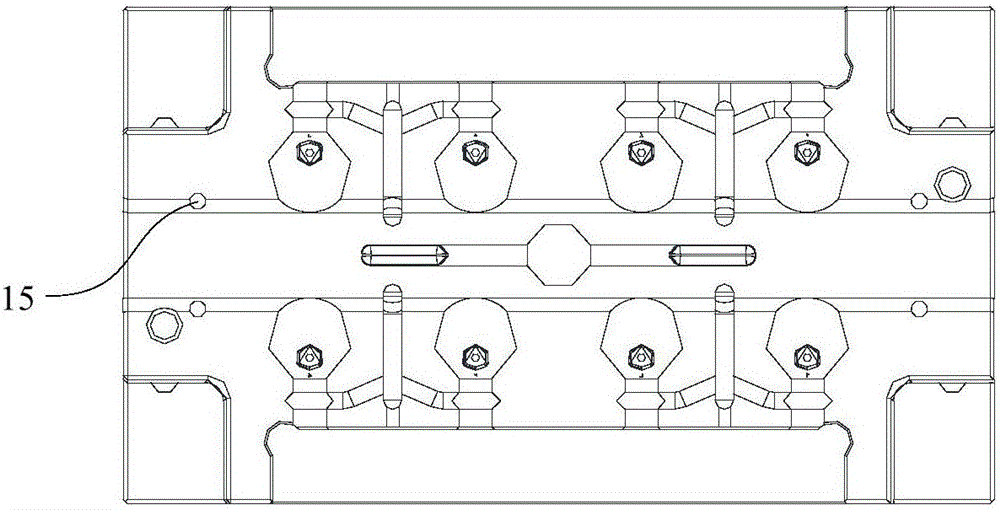
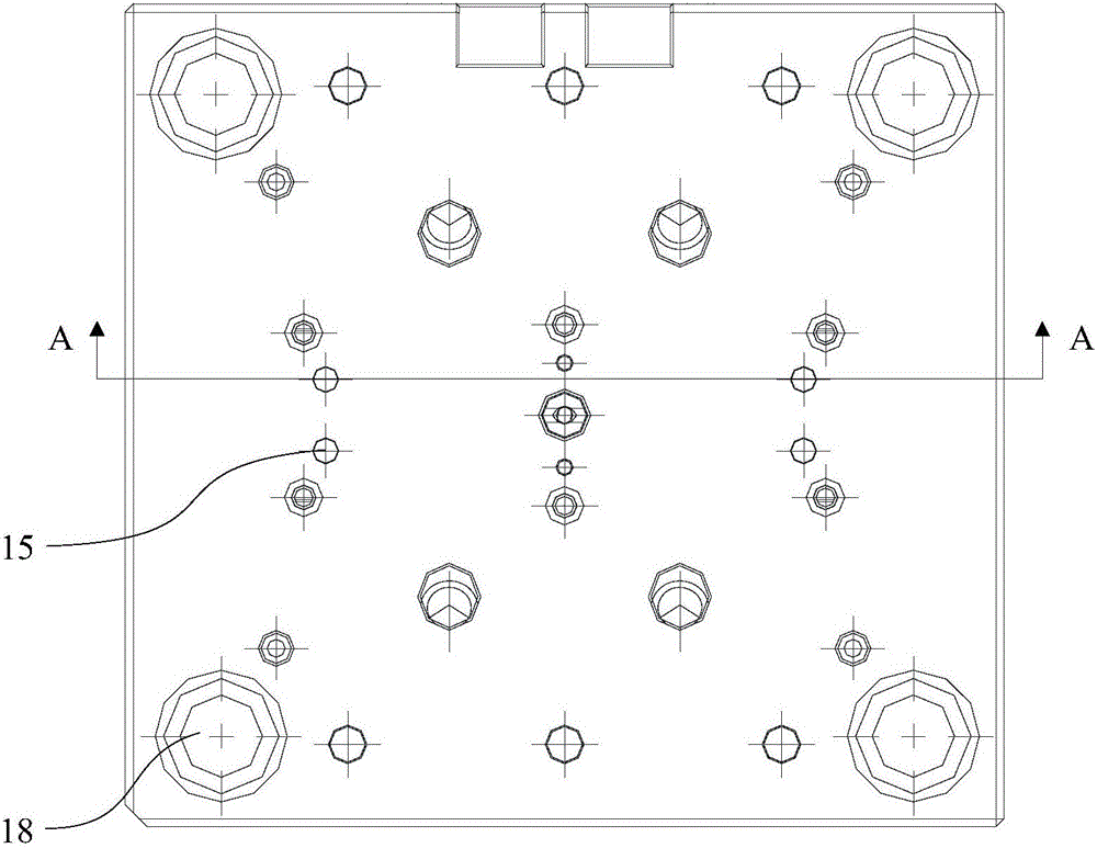
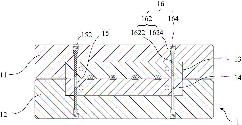
[0040] Refer below Figure 1 to Figure 5Describe the injection mold 1 and the processing and assembly process according to some embodiments of the present invention.

[0041] Such as Figure 1 to ...


PUM


Abstract

The invention provides an injection mold and a machining and assembling technology. The injection mold comprises a fixed mold plate, a movable mold plate, a first inner mold, a second inner mold, at least one datum hole and locating pieces, wherein the first inner mold and the second inner mold are installed in the fixed mold plate and the movable mold plate correspondingly, each datum hole penetrates through the fixed mold plate, the first inner mold, the second inner mold and the movable mold plate at the same time, and the locating pieces are inserted into the datum holes. According to the injection mold, through the uniform datum, the inner mold of the injection mold is machined according to the uniform datum, the machining datum is also used as the assembling datum, and the precise locating effect is achieved; and in this way, the defects that the frame forming precision is low, the datum faces of the inner molds deviate, screw receding locating is ineffective and the datums are respectively independent are overcome, the machining precision is improved, and finally the problems of dislocation, segment gaps and flashes of products are solved. The products are made to reach the ideal state that the appearance and the hand feeling are both good. Meanwhile, zero-error one-time machining is ensured, repeated machining and the risk of scraping of the inner molds are avoided, the products produced through the mold discharging one product once or the mold discharging multiple products once are significantly improved, and the mold precision is also significantly improved.

Description

technical field [0001] The invention relates to the field of molds, in particular to an injection mold and a processing and assembly process. Background technique [0002] At present, plastic products with one mold or multiple molds are prone to misalignment, step difference and batch front. For product quality, it is a fatal quality defect, whether it is in terms of feel or appearance requirements, it cannot meet the ideal state. Analyzing the reasons, there are mainly four aspects: 1. The frame opening accuracy of the A-plate and B-plate of the mold is not high, and deviations are prone to occur. 2. The reference plane of the inner mold deviates, is damaged or is reprocessed, so that the reference planes of the front and rear inner molds are not in the same plane. 3. There is a gap between the screws on the A board and the B board, which only play the role of tightening, but not positioning, so that the inner mold will run left and right and cannot be aligned. 4. Board ...

Claims


Application Information

Patent Timeline
Patent Type & Authority Applications(China)
IPC IPC(8): B29C45/26
CPCB29C45/2602B29C45/2606
Inventor 朱佳顺杨榕华王冰李健锋
Owner FOSHAN CITY SHUNDE DISTRICT BAINIAN TECH CO LTD
Why Eureka
Try Eureka