Novel wire feeding machine achieving automatic material replacing and continuous printing of material breakage

A wire feeder and material cutting technology, which is applied in metal processing equipment, 3D object support structures, manufacturing tools, etc., can solve the problems of difficult use of tailings, accidental material breaking and normal printing, etc., to achieve convenient operation and avoid single-wheel The wire feeding speed is not constant, and the effect of reducing labor costs

Active Publication Date: 2017-04-26
QINGDAO R & D INST XIAN JIAOTONG UNIV
View PDF7 Cites 7 Cited by
  • Summary
  • Abstract
  • Description
  • Claims
  • Application Information

AI Technical Summary

Problems solved by technology

[0004] The present invention aims at the above-mentioned problems that the tailings are difficult to use and the unexpected printing cannot be done due to accidental material breakage, etc., and provides a new type of wire feeder device for automatic material change and continuous printing when the material is broken

Method used


Image

  • Novel wire feeding machine achieving automatic material replacing and continuous printing of material breakage
  • Novel wire feeding machine achieving automatic material replacing and continuous printing of material breakage
  • Novel wire feeding machine achieving automatic material replacing and continuous printing of material breakage

Examples


Embodiment Construction

[0023] The present invention will be further described below in combination with specific embodiments.

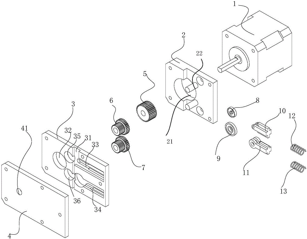
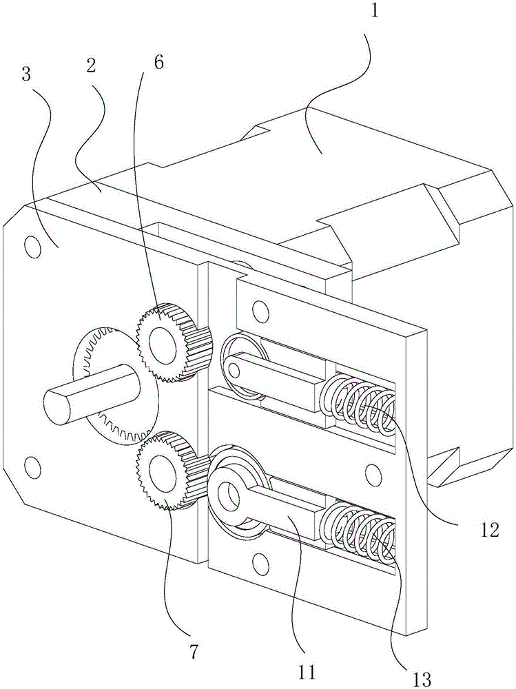
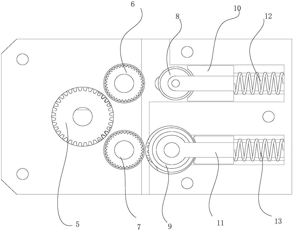
[0024] refer to Figure 1-3 , the new wire feeder of the present invention for automatic refueling and continuous printing after material breaking includes a motor 1 set in sequence, a wire feed wheel mounting plate 2, a bearing mounting plate 3 and a fixing plate 4; these four parts are connected in a detachable manner .

[0025] Wherein, a gear 5 is sheathed on the output shaft of the motor 1 , and a motor output shaft piercing hole 21 is provided on the fixed plate 4 . The wire feed wheel installation plate 2 is provided with a gear piercing hole 21, and the wire feed wheel installation plate 2 is also equipped with an upper wire feed wheel 6 and a lower wire feed wheel 7, and the gear 5 is connected with the upper and lower wire feed wheels. Wheels are meshed, driven by gears so that the upper and lower wire feed wheels rotate in the same direction and at the same spe...


PUM


Abstract

The invention provides a novel wire feeding machine achieving automatic material replacing and continuous printing of material breakage. The novel wire feeding machine achieving automatic material replacing and continuous printing of material breakage comprises a motor, a wire feeding wheel installing plate, a bearing installing plate and a fixing plate which are sequentially arranged; the four portions are connected in a detachable manner; an output shaft of the motor is sleeved with a gear; a gear penetrate-out hole is formed in the wire feeding wheel installing plate which is further provided with an upper wire feeding wheel and a lower wire feeding wheel; the gear is engaged with the upper wire feeding wheel and the lower wire feeding wheel; a wire feeding channel, an upper wire feeding wheel containing hole, a lower wire feeding wheel containing hole, an upper installing groove and a lower installing groove are formed in the bearing installing plate, and the upper wire feeding wheel containing hole and the lower wire feeding wheel containing hole are located in one side of the channel, and the upper installing groove and the lower installing groove are located in the other side of the channel; the wire feeding channel is divided into an upper segment and a lower segment; and the channel upper segment is communicated with the upper installing groove and the upper wire feeding wheel containing hole and can contain a plurality of wire materials side by side at the same time. By means of the novel wire feeding machine achieving automatic material replacing and continuous printing of material breakage, when the wire materials are used up or because of accidental wire breakage, continuous printing cannot be performed, it is not needed to temporarily stop the printing process, and manual material replacing is not needed.

Description

technical field [0001] The invention relates to a three-dimensional printer based on FDM fused deposition manufacturing technology, in particular to a new type of wire feeder for automatic material change and continuous printing when material is cut off. Background technique [0002] Three-dimensional printing technology began in the mid-1990s. According to different printing materials and molding methods, it can be divided into many types. Among them, Fused Lamination Modeling (FDM), that is, fused deposition 3D printing technology, has a simple structure, so The use of materials is easy to obtain, many advantages such as low manufacturing cost, are widely used. The 3D printer using fused lamination molding technology (FDM) heats and melts the filamentary hot-melt material, and at the same time, under the control of the computer, the 3D nozzle selectively coats the material on the workbench according to the cross-sectional profile information. After rapid cooling, a layer ...

Claims


Application Information

Patent Timeline
IPC IPC(8): B29C64/321B33Y30/00
CPCB33Y30/00
Inventor 李耀鹏李增辉张建勋毕利君
Owner QINGDAO R & D INST XIAN JIAOTONG UNIV
Why Eureka
Try Eureka