Cylinder barrel hoisting machine

A technology for cylinders and cranes, which is applied in the direction of load hanging components, transportation and packaging, etc., and can solve the problems of low automation and difficulty in transportation of cylinders

Inactive Publication Date: 2017-04-26
TIANJIN SHUANGXIANG ENG HYDRAULICS
View PDF5 Cites 2 Cited by
  • Summary
  • Abstract
  • Description
  • Claims
  • Application Information

AI Technical Summary

Problems solved by technology

[0003] The present invention aims to solve the technical problems of low degree of automation in cylinder cyl

Method used


Image

  • Cylinder barrel hoisting machine

Examples


Embodiment Construction

[0012] In order to further understand the invention content, characteristics and effects of the present invention, the following examples are given, and detailed descriptions are as follows in conjunction with the accompanying drawings:

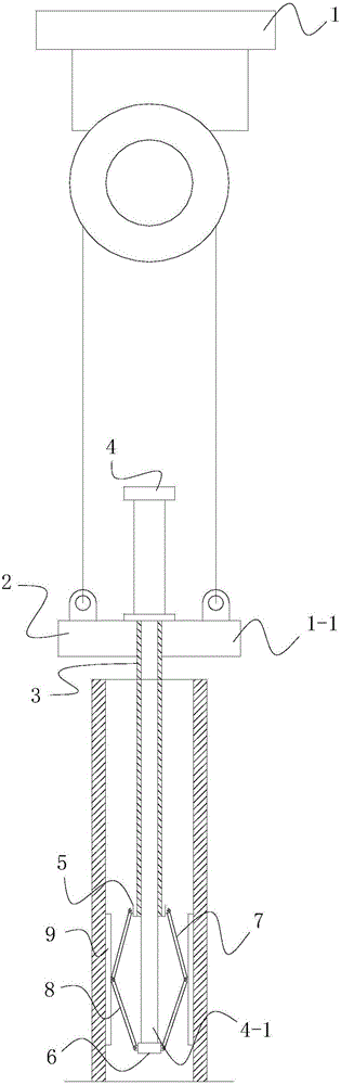
[0013] see figure 1 , including an electric hoist 1 and a suspension assembly; the electric hoist 1 has a lifting rope 1-1.

[0014] The hanging assembly includes a lifting frame 2, a sleeve pipe 3, a clamping cylinder 4, an upper sleeve body 5, a lower sleeve body 6, an upper expansion rod 7, a lower expansion rod 8, and an expansion top plate 9. The lifting frame 2 is connected with the suspension rope. The upper end of the sleeve pipe 3 is fixed on the lifting frame 2, the axis of the sleeve pipe 3 is vertically arranged, the clamping cylinder 4 is installed on the lifting frame 2, and the clamping cylinder 4 has a A vertically telescopic clamping lever 4-1, the clamping lever 4-1 is inserted in the sleeve 3, and the lower end of the cla...


PUM


Abstract

The invention relates to a cylinder barrel hoisting machine. The cylinder barrel hoisting machine comprises an electric block and a hanging assembly. The electric block is provided with a hanging rope. The hanging assembly comprises a vertical lifting frame, a casing pipe, a clamping air cylinder, an upper sleeve, a lower sleeve, an upper expansion rod, a lower expansion rod and an expansion ejector plate. The lifting frame is connected with the hanging rope. The upper end of the casing pipe is fixed to the lifting frame. The clamping air cylinder is installed on the lifting frame. A clamping lever of the clamping air cylinder is inserted in the casing pipe. The lower end of the clamping lever stretches out of the lower end of the casing pipe. The upper sleeve is fixed to the casing pipe, and the lower sleeve is fixed to the clamping lever. The upper end of the upper expansion rod is hinged to the upper sleeve, and the lower end of the upper expansion rod is hinged to the expansion ejector plate. The lower end of the lower expansion rod is hinged to the lower sleeve, and the upper end of the lower expansion rod is hinged to the expansion ejector plate. By means of equipment, rapid cylinder barrel hoisting can be achieved, labor force is saved, and the machining efficiency is improved.

Description

technical field [0001] The invention belongs to the technical field of mechanical production equipment, in particular to a cylinder hoist. Background technique [0002] During the manufacturing process of the hydraulic cylinder, it is necessary to transfer or move the parts of the cylindrical body. In the prior art, the transfer or movement of the cylindrical body is completed by manual handling, which has a low degree of automation and is time-consuming and laborious. Contents of the invention [0003] The present invention aims to solve the technical problems of low degree of automation of cylinder cylinder movement and high difficulty in transportation in the prior art, and provides a cylinder cylinder hoist. [0004] The technical solution adopted by the present invention to solve the technical problems existing in the known technology is: a cylindrical cylinder hoist, characterized in that it includes an electric hoist and a hanging assembly; the electric hoist has a ...

Claims


Application Information

Patent Timeline
IPC IPC(8): B66C1/56
CPCB66C1/56
Inventor 吕技选
Owner TIANJIN SHUANGXIANG ENG HYDRAULICS
Why Eureka
Try Eureka