A drying hanger with intelligent remote control

A remote control and hanger technology, applied in the field of drying racks, can solve the problems of poor use effect, idle hollow towel bar, waste of resources, etc., and achieve scientific and reasonable structural design, convenient handling and transportation, and good convenience in use Effect

Active Publication Date: 2019-05-21
KAIPING LEIJING WATER HEATING TECH DEV CO LTD
View PDF6 Cites 0 Cited by
  • Summary
  • Abstract
  • Description
  • Claims
  • Application Information

AI Technical Summary

Problems solved by technology

Since the hollow support rod is an integral rod-shaped structure, it will make the overall volume larger and cannot be disassembled, which brings a lot of inconvenience to handling and transportation
At the same time, the specifications of the towel rack have been fixed when it leaves the factory, and the corresponding number of hollow towel bars cannot be arranged according to actual needs, which may easily fail to meet the use requirements, or the hollow towel bars may be left idle, resulting in waste of resources
In the composition structure, its rotation is only realized by rotating the sleeve to cover the hollow support rod, and no limit positioning structure is set on the towel rod, so the rotation angle of the hollow towel rod cannot be positioned, and the process of placing the towel will cause The hollow towel bar rotates, which is prone to loose feeling, even under the action of a small external force, it will cause the hollow towel bar to swing or shake, and the use effect is poor

Method used


Image

  • A drying hanger with intelligent remote control
  • A drying hanger with intelligent remote control
  • A drying hanger with intelligent remote control

Examples


Embodiment Construction

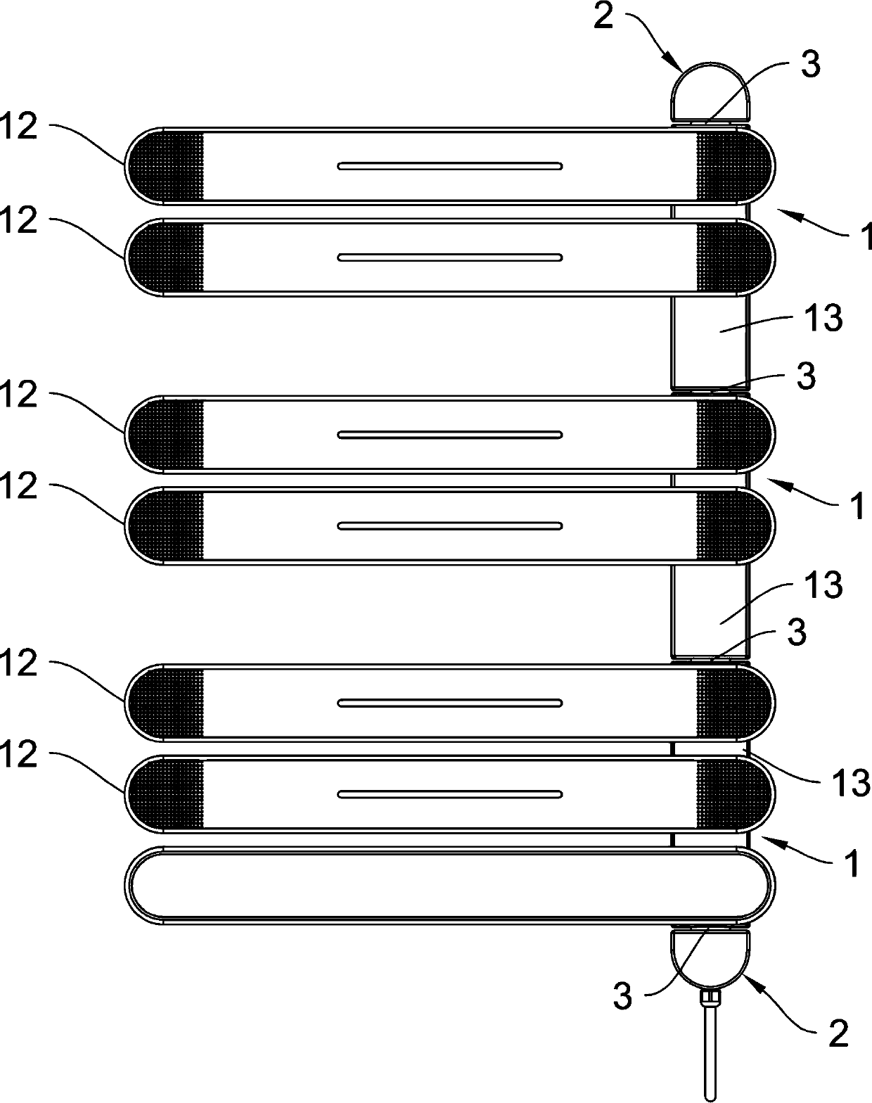
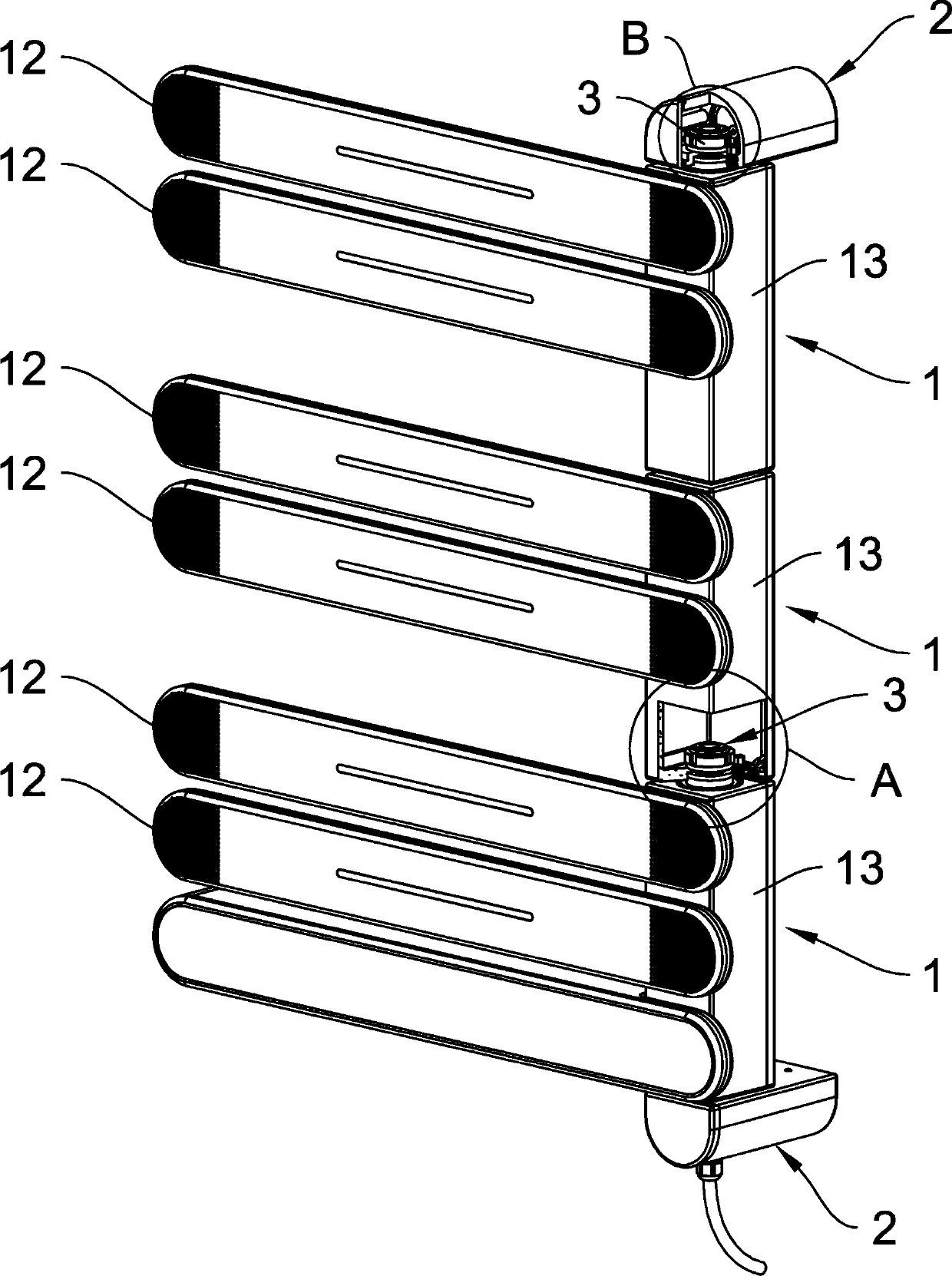
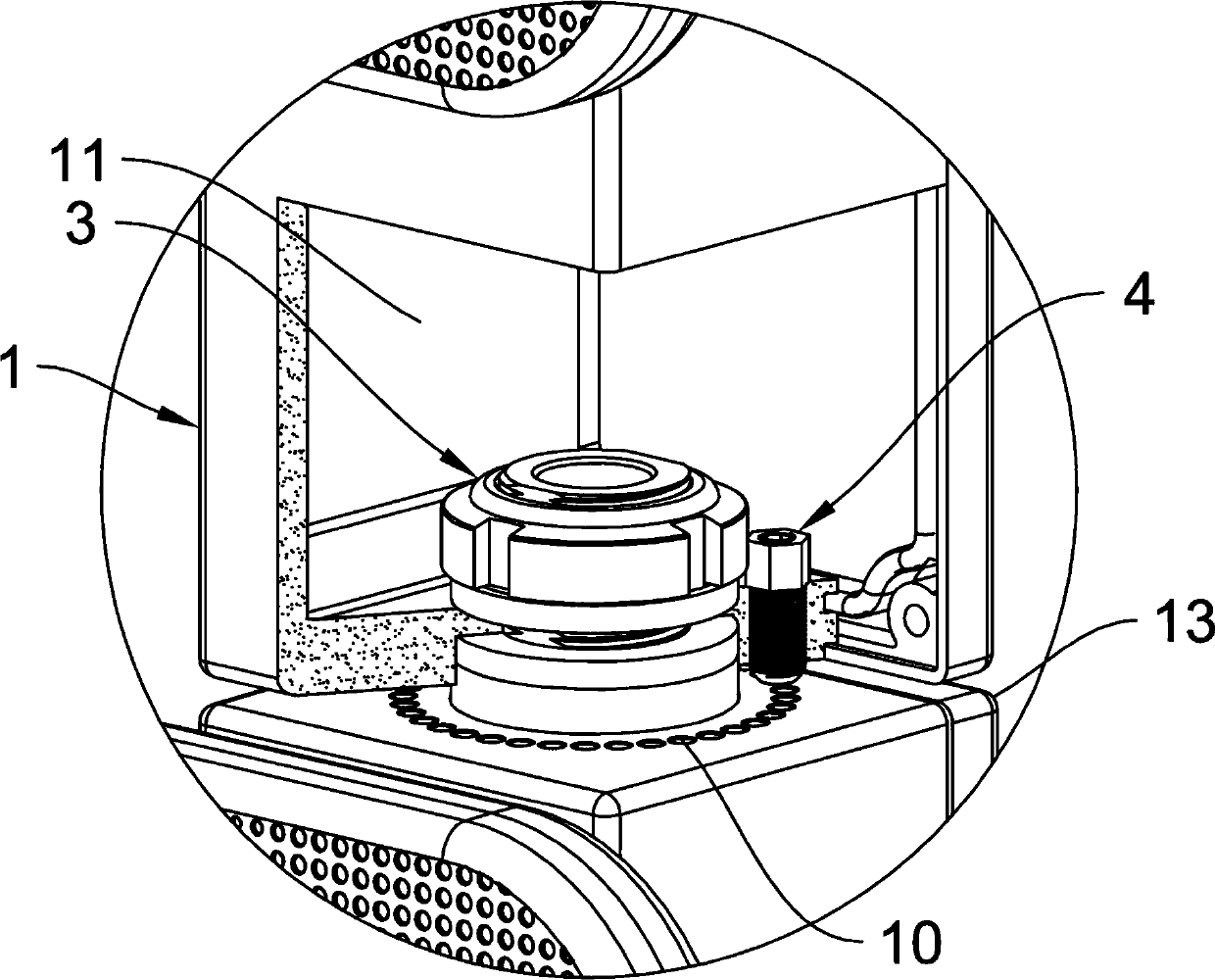
[0023] Such as figure 1 and Figure 4As shown, a drying hanger with intelligent remote control described in the present invention includes at least one cross bar hanger assembly 1, a fixed seat 2, a rotating connection mechanism 3, a damping mechanism 4, a wireless communication module, and a built-in intelligent The circuit module of the control chip, wherein each cross-bar hanger assembly 1 is respectively provided with a heating assembly, and the cross-bar hanger assembly 1 is connected with the fixed seat 2 through a rotating connection mechanism 3, and the cross-bar hanger assembly 1 realizes The fixed seat 2 is a fulcrum for left and right swinging rotation; the damping mechanism 4 is arranged on the side of the rotating connection mechanism 3 at the joint between the cross bar hanger assembly 1 and the fixed seat 2, and the damping mechanism 4 is provided with a spring positioning member 41 , the bouncing positioning member 41 acts on the positioning recess or the posi...


PUM


Abstract

The invention relates to a drying hanger with an intelligent remote control function. The drying hanger comprises the components of at least one cross bar hanger assembly, a fixing base, a rotatable connecting mechanism, a damping mechanism, a wireless communication module, and a circuit module which is internally provided with an intelligent control chip. The cross bar hanger assembly is provided with a heating assembly. The cross bar hanger assembly is connected with the fixing base through the rotatable connecting mechanism. The damping mechanism is arranged beside the rotatable connecting mechanism at the connecting part between the cross bar hanger assembly and the fixing base. The damping mechanism is provided with a bouncing position fixing member. The bouncing position fixing member acts on the cross bar hanger assembly or the fixing base. The circuit module is arranged on the cross bar hanger assembly or the fixing base. The wireless communication module is arranged on the circuit module. The drying hanger has advantages of high flexibility and high variety in use, wide application range, flexible swinging and accurate position fixing of the cross bar hanger assembly, no random swinging, better use effect, convenient packaging, convenient conveying, convenient transportation, and effective realization of a drying function and a remote control function.

Description

technical field [0001] The invention relates to a drying rack for hanging towels, bath towels or clothes. Background technique [0002] The published patent document with the Chinese patent application number CN201210384742.X discloses a technical solution titled "humidity-sensing disinfection and drying towel rack". The technical solution discloses the following technical features: fan assembly, hollow support rod, The two ends of the hollow support rod are provided with fixed brackets, the hollow support rod is provided with a rotating sleeve, and the rotating sleeve is provided with a hollow towel bar. Since the hollow support rod is an integral rod-shaped structure, the overall volume is large and cannot be disassembled, which brings a lot of inconvenience to handling and transportation. At the same time, the specifications of the towel rack have been fixed when it leaves the factory, and the corresponding number of hollow towel bars cannot be arranged according to actu...

Claims


Application Information

Patent Timeline
Patent Type & Authority Patents(China)
IPC IPC(8): D06F58/00D06F58/20D06F58/26D06F58/28
CPCD06F58/00D06F58/20D06F58/203D06F58/26D06F58/30
Inventor 方南翔
Owner KAIPING LEIJING WATER HEATING TECH DEV CO LTD
Why Eureka
Try Eureka