

Full-automatic cloth paving and cutting integrated machine
A fully automatic, all-in-one machine technology, applied in the cutting of textile materials, thin material processing, spreading thin soft materials, etc., can solve the problems of delaying fabric processing time and limiting fabric processing efficiency, and achieve a smooth and smooth spreading process. Prevent jamming and improve processing efficiency
- Summary
- Abstract
- Description
- Claims
- Application Information
AI Technical Summary
Problems solved by technology
Method used
Image

Examples
Embodiment Construction
[0070] The present invention will be further described in detail below in conjunction with the accompanying drawings. Wherein, the descriptive terms such as up, down, left, right, etc. are used for the description, with the purpose of helping readers to understand, but not intended to limit.
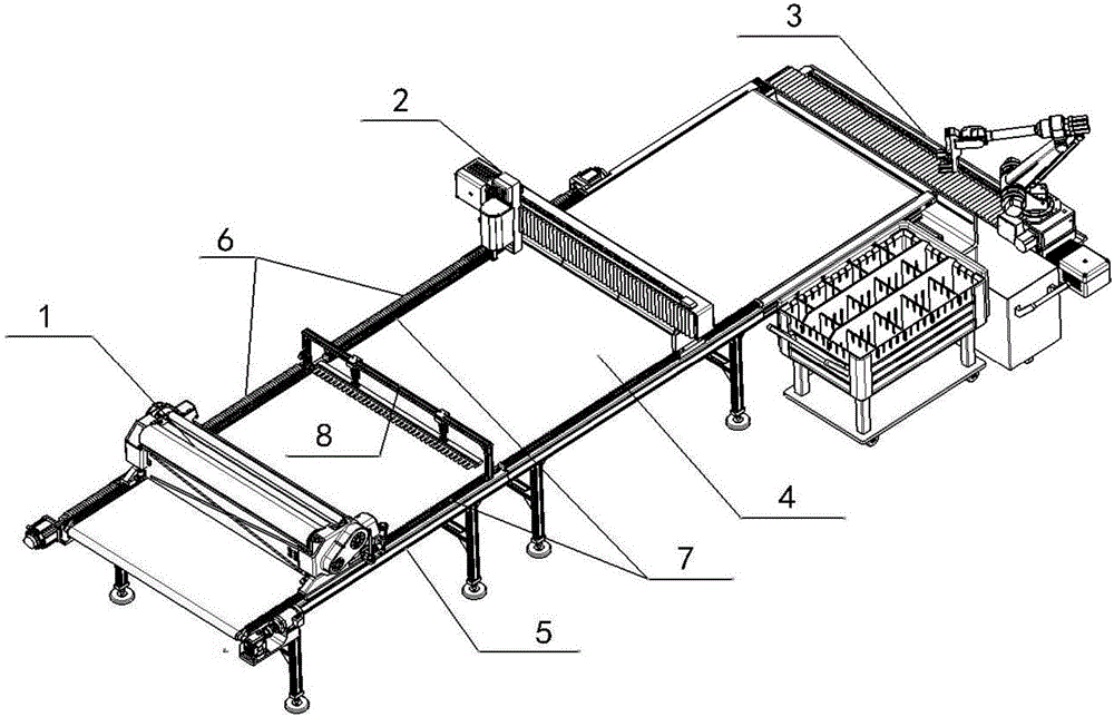
[0071] Such as Figure 1 to Figure 10 As shown, the fully automatic cloth spreading and cutting machine includes cutting table 5, cloth spreading machine 1, cloth spreading machine walking mechanism, spreading and pressing mechanism 8, cloth cutting machine 2 and cloth cutting machine walking mechanism;
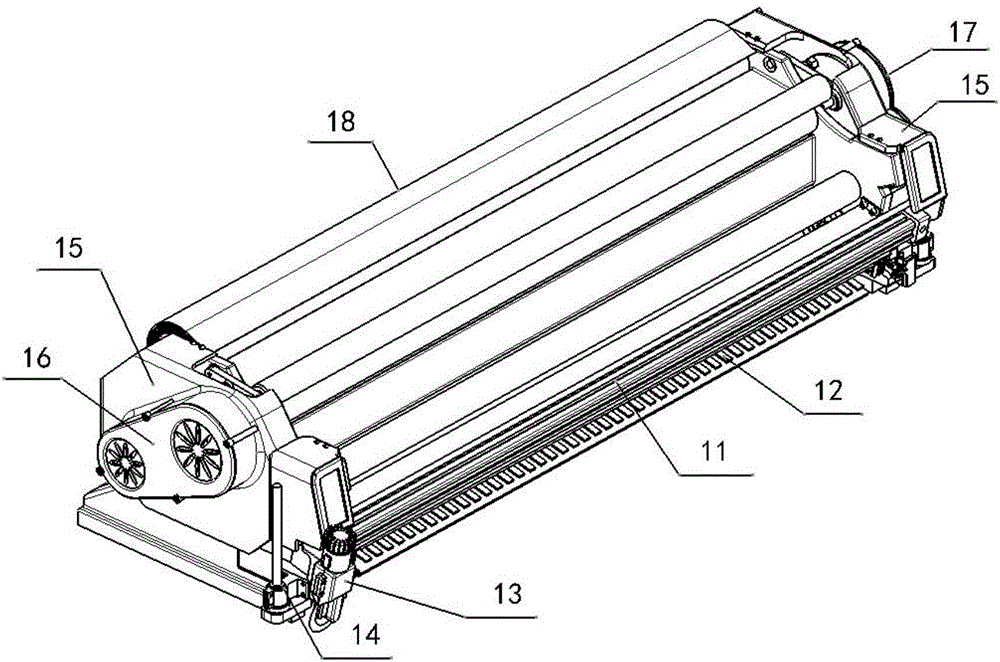
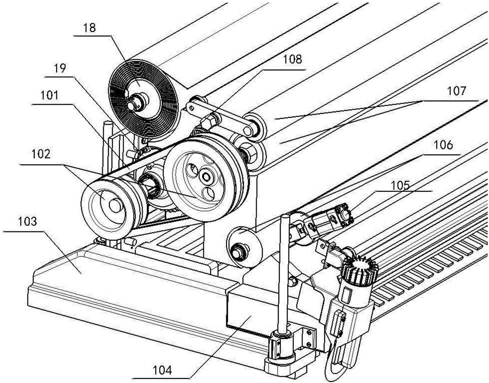
[0072] The spreading machine 1 includes a machine base, a cloth shaft and a cloth breaking mechanism; the machine base is in the shape of a strip as a whole, and the cloth shaft is in the shape of a strip parallel to the length direction of the machine base, and is rotatable Installed on the machine base; the cloth breaking mechanism includes a rodless cylinder 11 for cloth breaking an...
PUM
 Abstract
Description
Claims
Application Information