Railway line subsidiary facilities and mounting method thereof

A technology for ancillary facilities and railway lines, applied in the fields of bridge engineering and railway lines, which can solve the problems of non-insulating performance of metal materials, physical damage of maintenance personnel, and increased construction period, so as to save maintenance and protection costs, integrity and cross-sectional shape The effect of good consistency and high production efficiency

Inactive Publication Date: 2017-04-26
CHINAGRATE COMPOSITES STRUCTURE NANTONG
View PDF17 Cites 3 Cited by
  • Summary
  • Abstract
  • Description
  • Claims
  • Application Information

AI Technical Summary

Problems solved by technology

This increases the construction period and increases the labor intensity; at present, the auxiliary facilities materials used on the beam body are metal and concrete, and the materials are not only heavy, but also increase the load of the beam body, and improve the support for the beam body and the beam body. Structural strength requirements for uprights
In addition, metal materials have no insulating properties, and if there is a leakage, the entire railway line will be paralyzed
Since the metal auxiliary facilities are exposed to the air for a long time, they are easy to rust, so a large amount of money is required for maintenance every year, which will cause damage to the body of the maintenance personnel and damage the environment during the maintenance process.

Method used


Image

  • Railway line subsidiary facilities and mounting method thereof
  • Railway line subsidiary facilities and mounting method thereof
  • Railway line subsidiary facilities and mounting method thereof

Examples


Embodiment Construction

[0054] In order to make the purpose, technical solutions and advantages of the embodiments of the present invention clearer, the technical solutions in the embodiments of the present invention will be clearly and completely described below. Obviously, the described embodiments are part of the embodiments of the present invention, not all of them. the embodiment. Elements and features described in one embodiment of the present invention may be combined with elements and features shown in one or more other embodiments. It should be noted that representation and description of components and processes that are not related to the present invention and that are known to those of ordinary skill in the art are omitted from the description for the purpose of clarity. Based on the embodiments of the present invention, all other embodiments obtained by persons of ordinary skill in the art without making creative efforts belong to the protection scope of the present invention.

[0055] ...


PUM

PropertyMeasurementUnit
Thicknessaaaaaaaaaa
Diameteraaaaaaaaaa
Diameteraaaaaaaaaa

Abstract

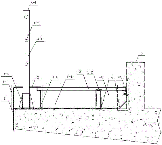
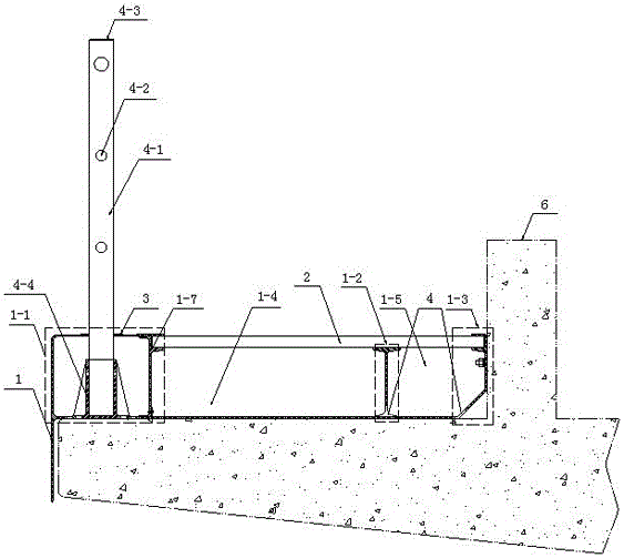
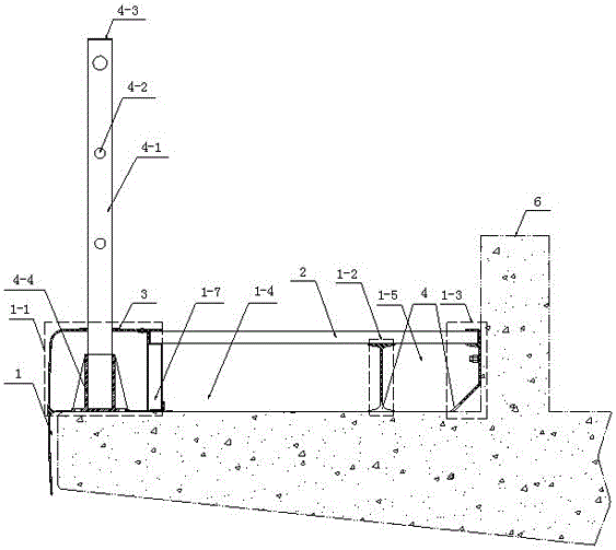
The invention discloses railway line subsidiary facilities. The railway line subsidiary facilities are mounted on a beam body, the subsidiary facility on one side of the beam body is the guardrail section subsidiary facility, and the subsidiary facility on the other side of the beam body is the sound barrier section subsidiary facility. The guardrail section subsidiary facility is composed of an integral type curtain plate structure or an assembling type curtain plate structure, a guardrail, a trail plate and a decorating plate. The sound barrier section subsidiary facility is composed of an integral type curtain plate structure or an assembling type curtain plate structure, a sound barrier upright column, a sound barrier base, a trail plate and a decorating plate. The railway line subsidiary facility products are produced by a pultrusion process, and the products have the characteristics of lightweight, high strength, high bearing capacity, no transformation, no moisture absorption, stable size, chemical corrosion resistance, ageing resistance, good shock absorption property, no electric conduction, simple structure, convenient on-site installation and the like.

Description

technical field [0001] The invention relates to a railway line and bridge engineering, in particular to an auxiliary facility used in a railway box girder and an installation method thereof. Background technique [0002] With the development and needs of my country's economy, the scale of railway construction is gradually increasing, and it is faced with complex problems such as terrain, geology, and environment. In railway construction, in order to reduce the columns supporting the beam of the railway line, the length of the beam is designed The growth has been carried out, which puts forward new requirements for the load design required by the beam body. In order to make the beam body meet the load, it is necessary to reduce the weight of all the ancillary facilities of the beam body. According to the traditional beam body production process, firstly after the beam body is manufactured by the enterprise, the beam body is transported to the site for installation, and the com...

Claims


Application Information

Patent Timeline
IPC IPC(8): E01F8/00E01D19/00E01D19/10E01D21/00E01D101/40E01D101/30
CPCE01D19/00E01D19/103E01D21/00E01F8/0017E01F8/0023E01D2101/40E01D2101/30
Inventor 张跃进赵沭通
Owner CHINAGRATE COMPOSITES STRUCTURE NANTONG
Why Eureka
Try Eureka