Combination type excavator bucket tooth and die-forging method for tooth tip of combination type excavator bucket tooth

An excavator bucket tooth and combined technology, which is applied to the die forging field of combined excavator bucket teeth and their tooth tips, can solve the problems of unsustainable tooth tips, inconvenient disassembly and replacement of the combined bucket teeth, etc. Simple and practical structure, reasonable connection structure

Inactive Publication Date: 2017-04-26
永平县建达鑫鑫合金铸造有限公司
View PDF8 Cites 3 Cited by
  • Summary
  • Abstract
  • Description
  • Claims
  • Application Information

AI Technical Summary

Problems solved by technology

[0004] The purpose of the present invention is to overcome the deficiencies of the prior art, to provide a combined excavator bucket tooth and its tip forging method, to solve the problem of inconvenient replacement of combined bucket teeth, and the problem that the tooth tip is not durable

Method used


Image

  • Combination type excavator bucket tooth and die-forging method for tooth tip of combination type excavator bucket tooth
  • Combination type excavator bucket tooth and die-forging method for tooth tip of combination type excavator bucket tooth
  • Combination type excavator bucket tooth and die-forging method for tooth tip of combination type excavator bucket tooth

Examples


Embodiment 1

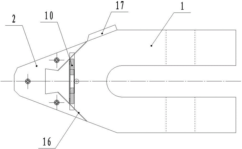
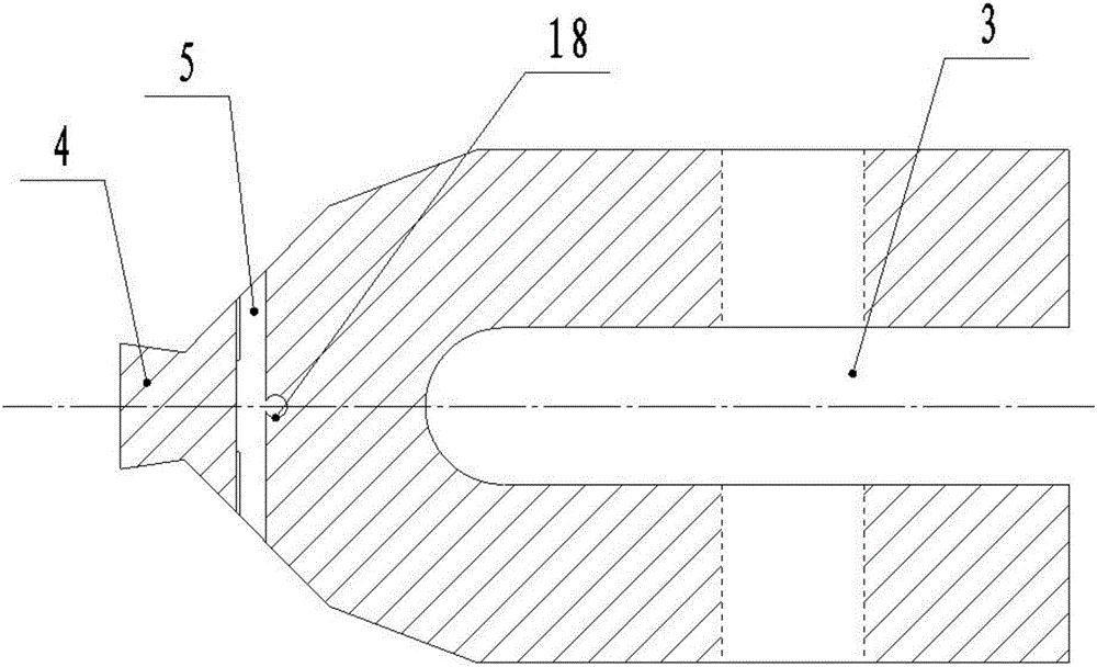
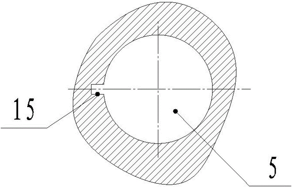
[0040] Such as Figure 1-6 As shown, a combined excavator bucket tooth of the present invention includes a tooth seat 1 and a tooth tip 2. The rear end of the tooth seat 1 is provided with a bucket lip installation opening 3, and the front end of the tooth seat 1 is provided with a tooth tip 2. A dovetail block 4, a pin hole 5 is provided at the joint between the front part of the tooth seat 1 and the tooth tip 2; the tooth tip 2 includes a middle tooth 6 and a guard side plate 7, and the two sides of the middle tooth 6 are respectively provided with guard sides Plate 7, the rear end of the middle tooth 6 is provided with a tooth seat installation port 8, the front end of the tooth seat installation port 8 is provided with a dovetail groove 19 cooperating with the dovetail block 4, and the upper lip and the lower lip of the tooth seat installation port 8 are respectively provided with There is a blind pin hole 9 corresponding to the pin hole 5 , and the middle tooth 6 is locke...

Embodiment 2

[0046] Such as Figure 4-5 As shown, a tooth tip die forging method of the present invention, the tooth tip 2 adopts A-100 alloy steel die forging forming, and the die forging process of the tooth tip 2 includes the following steps:

[0047] Step 1: cutting;

[0048] Step 2: The billet is machined; the heating process of the billet in step 2 is as follows: firstly, the temperature in the electric furnace is raised to 850°C, and then kept for 60 minutes, and then the temperature in the electric furnace is raised to 1050°C, and kept for 30 minutes; preheating of the mold in step 2 The temperature is 250°C-350°C, and the preheating time is 2 hours.

[0049] Step 3: Put the machined billet into the electric furnace for heating;

[0050]Step 4: Use a free forging hammer to forge, and air cool after completing the forging;

[0051] Step 5: Put the block into the electric furnace to heat, and preheat the mold at the same time; the heating process of the block in step 5 is to first...


PUM


Abstract

The invention discloses a combination type excavator bucket tooth and a die-forging method for a tooth tip of the combination type excavator bucket tooth. The combination type excavator bucket tooth comprises a tooth seat and the tooth tip; a bucket lip mounting opening is formed in the rear end of the tooth seat; a dovetail block which is in connected installation with the tooth tip is arranged at the front end of the tooth seat; a pin hole is formed in a connecting position between the front part of the tooth seat and the tooth tip; the tooth tip comprises a middle tooth and tooth protecting side plates; the tooth protecting side plates are respectively arranged on the two sides of the middle tooth; a tooth seat mounting opening is formed in the rear end of the middle tooth; a dovetail groove which is in matched installation with the dovetail block is formed in the front end of the tooth seat mounting opening; blind pin holes corresponding to the pin hole are respectively formed in the upper lip and the lower lip of the tooth seat mounting opening; the middle tooth is locked on the tooth seat through an adjustment pin shaft assembly which is arranged in the pin hole. The connecting structure of the tooth tip and the tooth seat is reasonable; the tooth tip cannot lose easily after long-time use; the tooth tip is convenient to detach and replace.

Description

technical field [0001] The invention relates to the field of excavators, in particular to a die forging method for combined excavator bucket teeth and tooth tips thereof. Background technique [0002] Excavator bucket teeth are typical wear parts of excavating equipment. Bucket teeth are severely worn during use, and parts are replaced frequently. In order to reduce the cost of bucket teeth, it is usually designed as a combined structure. [0003] The existing combined bucket teeth also have the following defects: the connection structure of the tooth tip and the tooth seat is unreasonable, and the tooth tip is lost due to long-term use; it is inconvenient to replace; Alloy steel materials have good comprehensive mechanical properties and are not prone to breakage. However, low alloy steel materials wear more seriously. When they are worn out to the point where they cannot protect, they need to be replaced. Frequent replacement of bucket teeth not only makes the The effic...

Claims


Application Information

Patent Timeline
Patent Type & Authority Applications(China)
IPC IPC(8): E02F9/28B21J1/06B21K5/12C21D9/00
CPCB21J1/06B21K5/12C21D9/0068E02F9/2808E02F9/2833E02F9/2858Y02P10/20
Inventor 羊实
Owner 永平县建达鑫鑫合金铸造有限公司
Why Eureka
Try Eureka