Microwave anechoic chamber

A technology of microwave anechoic chamber and absorbing material, applied in the field of measurement, can solve problems such as increasing the manufacturing cost of anechoic chamber, and achieve the effects of easy operation, improved measurement accuracy and low cost

Pending Publication Date: 2017-04-26
GENERAL TEST SYST
View PDF10 Cites 8 Cited by
  • Summary
  • Abstract
  • Description
  • Claims
  • Application Information

AI Technical Summary

Problems solved by technology

This solution will also increase

Method used


Image

  • Microwave anechoic chamber
  • Microwave anechoic chamber
  • Microwave anechoic chamber

Examples


Embodiment Construction

[0036] Embodiments of the present invention will be described in detail below. It should be emphasized that the following descriptions are only exemplary and intended to explain the present invention, but should not be construed as limiting the present invention.

[0037] In addition, the terms "first" and "second" are used for descriptive purposes only, and cannot be interpreted as indicating or implying relative importance or implicitly specifying the quantity of indicated technical features. Thus, a feature defined as "first" and "second" may explicitly or implicitly include one or more of these features. In the description of the present invention, "plurality" means two or more, unless otherwise specifically defined.

[0038] In the present invention, unless otherwise clearly specified and limited, terms such as "installation", "connection", "connection" and "fixation" should be understood in a broad sense, for example, it can be a fixed connection or a detachable connect...


PUM


Abstract

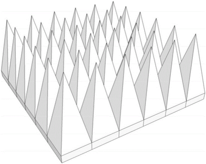
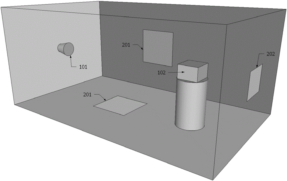
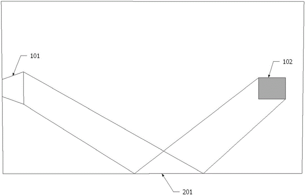
The invention discloses a microwave anechoic chamber which comprises an electromagnetic shielding room and also comprises a wave absorbing material and a measurement antenna installed at the inner wall of the electromagnetic shielding room. At least the upper part of the wave absorbing material is a periodic pyramid. The microwave anechoic chamber is characterized in that at least the edge direction of the pyramid of the wave absorbing material in the main reflection area of non-vertical incidence faces a main incoming wave direction in the microwave anechoic chamber. Through a simple mode with easy operation and low cost, under the condition of not changing an anechoic chamber structure or the height of the wave absorbing material, only through changing the layout of the wave absorbing material, can the anechoic chamber reflection, can the anechoic chamber reflection be reduced greatly, a more pure measurement environment is created, and the measurement precision is improved.

Description

technical field [0001] The invention relates to the technical field of measurement, in particular to a microwave anechoic chamber for wireless performance parameter measurement. Background technique [0002] Microwave anechoic chamber, also known as echo-free chamber, non-reflection chamber or absorbing anechoic chamber (hereinafter referred to as anechoic chamber), is to lay absorbing material on the inner wall (wall, floor, ceiling, etc.) The electromagnetic wave can reduce or eliminate reflection and scattering, thus forming the free space condition required for antenna measurement. Microwave anechoic chamber is widely used in antenna parameter measurement and ideal place for electromagnetic wave diffraction, scattering and radiation characteristic measurement. The most basic function of microwave anechoic chamber is to provide a stable and controllable electromagnetic signal environment that meets the requirements of measurement. According to the different installation...

Claims


Application Information

Patent Timeline
IPC IPC(8): G01R29/10
CPCG01R29/105
Inventor 漆一宏于伟罗庆春沈鹏辉
Owner GENERAL TEST SYST
Why Eureka
Try Eureka