Voltage calibration method, magnetic resonance imaging method and system
A technology of magnetic resonance imaging and voltage calibration, which is applied in the direction of using the nuclear magnetic resonance imaging system for measurement, magnetic resonance measurement, and measurement of magnetic variables. and other problems, to achieve the effect of improving voltage calibration accuracy, reducing the influence of uniformity and contrast, and improving image quality
- Summary
- Abstract
- Description
- Claims
- Application Information
AI Technical Summary
Problems solved by technology
Method used
Image

Examples
Embodiment 1
[0066] An embodiment of the present invention provides a voltage calibration method, and the flow of the voltage calibration method can be applied to the calibration of radio frequency transmission voltage of a radio frequency system in a magnetic resonance imaging system.
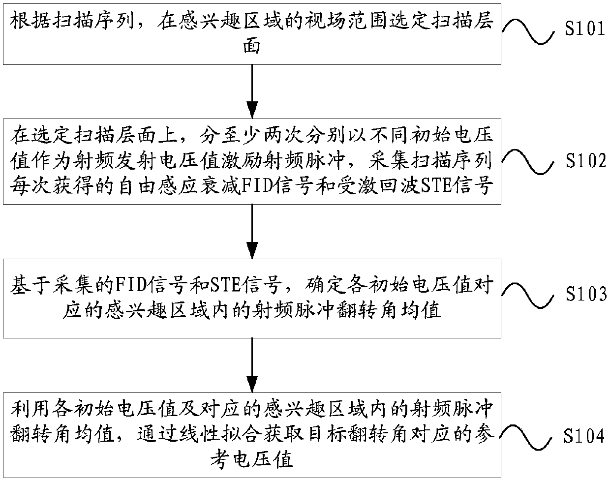
[0067] figure 1 An example flow chart of the voltage calibration method provided by the embodiment of the present invention. Such as figure 1 As shown, in this embodiment, the voltage calibration method may include the following steps:
[0068] S101, according to the scanning sequence, select a scanning layer in the field of view of the region of interest;
[0069] S102, on the selected scanning level, excite the radio frequency pulse at least twice with different initial voltage values as the radio frequency transmission voltage value, and collect the free induction attenuation FID signal and the stimulated echo STE signal obtained each time in the scanning sequence;
[0070] S103, based on the colle...
example 1
[0088] In this example, two-point fitting is used for voltage calibration, and the voltage calibration process is as follows:
[0089] a1, according to the scanning sequence, obtain the FOV (Field of View, field of view) size, position information and slice group information of the pancreatic region, and set the position information and slice group information into the calibration sequence;
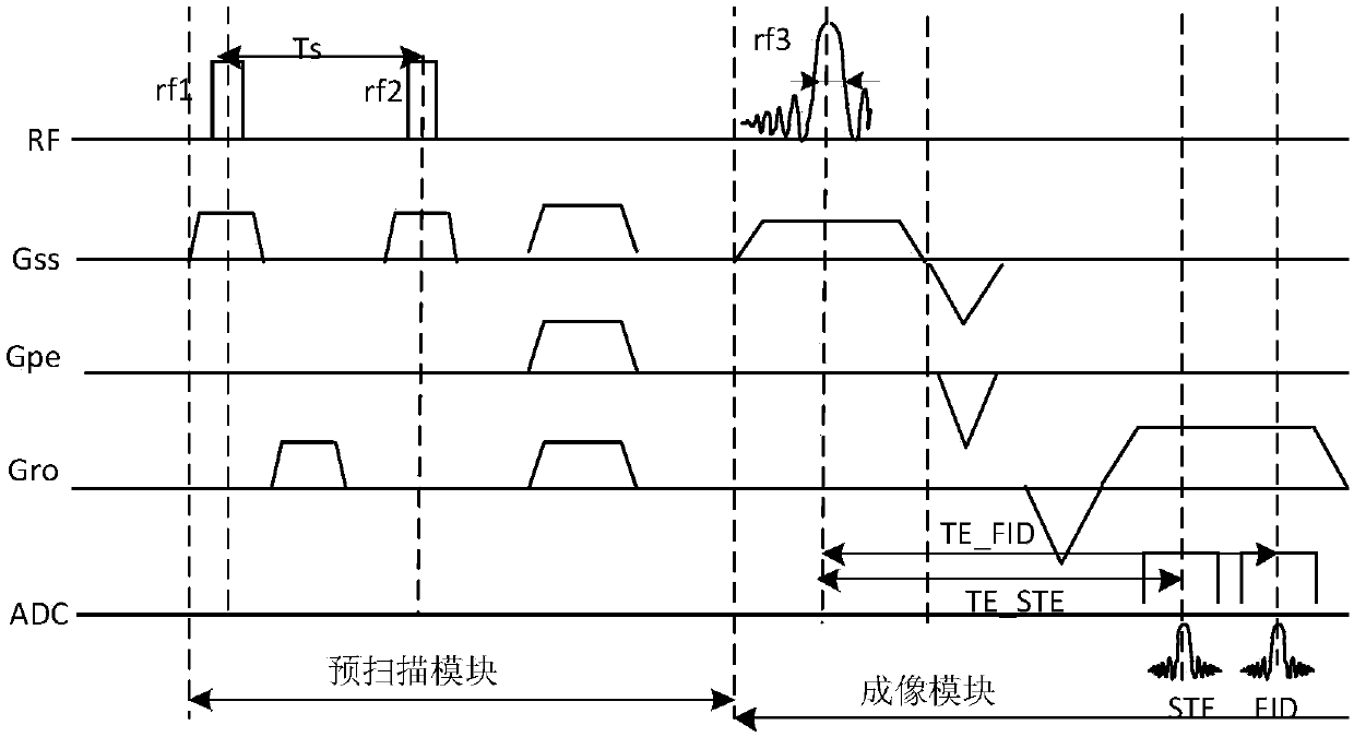
[0090] figure 2 An example diagram of the scanning sequence. figure 2 Among them, the scan sequence includes a pre-scan sequence and an imaging sequence, and the pre-scan sequence may also be called a calibration sequence, and the calibration sequence is a layer-selected DREAM (Dual Refocusing Echo Acquisition Mode, dual focusing echo acquisition mode) sequence. Among them, RF (radio Frequency) is the radio frequency transmission pulse; Gss (sliceselect gradient) is the layer selection gradient; Gpe (phase encoding gradient) phase encoding gradient; Gro (readout gradient) is the readou...
example 2
[0113] In this example, three-point fitting is used for voltage calibration, and the voltage calibration process is as follows:
[0114] b1, according to the scanning sequence, obtain the FOV size, position information and slice group information of the pancreas area, and set the position information and slice group information into the calibration sequence;
[0115] figure 2 An example diagram of the scanning sequence. figure 2 Among them, the scan sequence includes a pre-scan sequence and an imaging sequence, and the pre-scan sequence may also be called a calibration sequence, and the calibration sequence is a layer-selected DREAM (Dual Refocusing Echo Acquisition Mode, dual focusing echo acquisition mode) sequence.
[0116] b2, on the selected abdominal level, the initial voltage values V1, V2 and V3 were respectively used as the RF emission voltage values to excite the RF pulses three times, and the FID signals and STE signal;
[0117] Among them, V1=factor1*V in...
PUM
 Abstract
Description
Claims
Application Information
 - R&D
- Intellectual Property
- Life Sciences
- Materials
- Tech Scout
- Unparalleled Data Quality
- Higher Quality Content
- 60% Fewer Hallucinations
Browse by: Latest US Patents, China's latest patents, Technical Efficacy Thesaurus, Application Domain, Technology Topic, Popular Technical Reports.
© 2025 PatSnap. All rights reserved.Legal|Privacy policy|Modern Slavery Act Transparency Statement|Sitemap|About US| Contact US: help@patsnap.com