Microscope optical splicing system and method

A technology of optical splicing and microscope system, which is applied in the field of optics to achieve the effects of improved work efficiency, good consistency, and fast assembly and adjustment

Pending Publication Date: 2017-04-26
XI'AN INST OF OPTICS & FINE MECHANICS - CHINESE ACAD OF SCI
View PDF0 Cites 0 Cited by
  • Summary
  • Abstract
  • Description
  • Claims
  • Application Information

AI Technical Summary

Problems solved by technology

Based on the current domestic manufacturing capacity of microlens arrays, an overall microlens array with a length, width, and curvature radius of millimeters has not been successfully developed. Therefore, at present, a microlens array of this size can only be achieved by splicing a single microlens.

Method used


Image

  • Microscope optical splicing system and method
  • Microscope optical splicing system and method
  • Microscope optical splicing system and method

Examples


Embodiment Construction

[0028] The microlens optical splicing system of the present invention will be described in detail below.

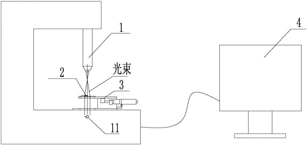
[0029] Such as Figure 1 to Figure 3 As shown, the microlens optical splicing system mainly includes a microscope system 1, a two-dimensional adjustment table 3 and a monitor 4; the microscope system 1 is connected to the monitor 4; the two-dimensional adjustment table 3 is installed on the platform of the microscope system 1 and located on the microscope lens below;

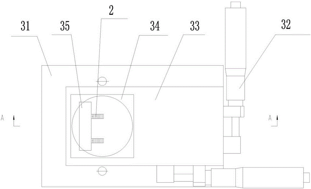
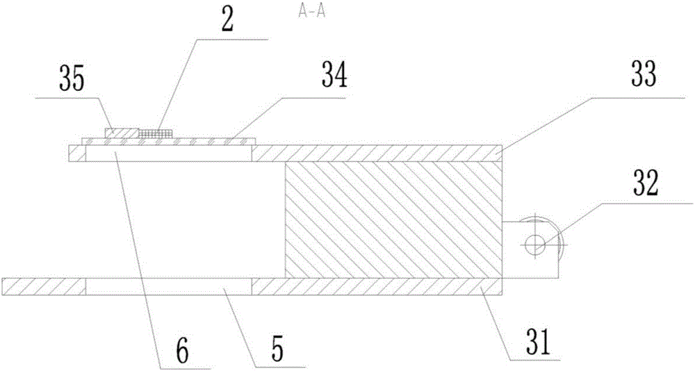
[0030] The two-dimensional adjustment table 3 includes a base 31, a two-dimensional adjustment mechanism 32, a connecting plate 33, a glass plate 34 and a splicing substrate 35; Circular hole 6; the first circular hole 5 and the second circular hole 6 are coaxially arranged; the two-dimensional adjustment mechanism 32 is installed on the base 31, the connection plate 33 is installed on the two-dimensional adjustment mechanism 32, and the glass plate 34 is installed on the connection plate 33 and located o...


PUM


Abstract

The invention relates to a microscope optical splicing system and method. The system comprises a microscope system, a two-dimensional adjusting stand and a monitor, wherein the microscope system is connected with the monitor, the two-dimensional adjusting stand is mounted on a platform of the microscope system, is below a microscope lens and comprises a foundation, a two-dimensional adjusting mechanism, a connection board, a flat glass board and a splicing substrate, the foundation is provided with a first circular hole corresponding to a light source of the microscope system, the connection board is provided with a second circular hole, the first circular hole and the second circular hole are coaxially arranged, the two-dimensional adjusting mechanism is mounted on the foundation, the connection board is mounted on the two-dimensional adjusting mechanism, the flat glass board is mounted on the connection board and is further on the first circular hole, and the splicing substrate is mounted on the flat glass board. The system is advantaged in that a bottleneck problem that microscope arrays can not be processed and manufactured in the prior art is solved.

Description

technical field [0001] The invention belongs to the field of optical technology, and in particular relates to a microlens optical splicing system and method. Background technique [0002] In recent years, with the development of laser technology, existing lasers have been able to provide the laser power required for propulsion of on-orbit micro-nano satellites, which makes it possible to apply laser micro-propulsion technology to micro-nano satellites at the current technical level. [0003] Laser micro thruster is a new type of micro propulsion system, which is mainly used for orbit keeping, attitude control and orbit maneuvering of micro spacecraft. The micro-lens array spliced ​​by the micro-lens optical splicing system studied in this paper is mainly used for micro-focusing of single-pulse laser arrays in laser micro-thrusters. Based on the current domestic manufacturing capacity of microlens arrays, an overall microlens array with millimeter-scale length, width, and cu...

Claims


Application Information

Patent Timeline
IPC IPC(8): G02B7/02
CPCG02B7/021G02B7/025
Inventor 初昶波张昊苏徐亮段亚轩李智勇
Owner XI'AN INST OF OPTICS & FINE MECHANICS - CHINESE ACAD OF SCI
Why Eureka
Try Eureka