Magnetic coupling wireless charging device having properties of high efficiency and high safety factor

A technology of wireless charging and safety factor, which is applied in the direction of circuit devices, battery circuit devices, current collectors, etc., can solve the problems of not being able to effectively improve the efficiency of magnetic coupling wireless charging, etc., to solve the problem of insufficient safety, increase work efficiency, and optimize the structure The effect of the design

Pending Publication Date: 2017-04-26
伽行科技(北京)有限公司
View PDF0 Cites 4 Cited by
  • Summary
  • Abstract
  • Description
  • Claims
  • Application Information

AI Technical Summary

Problems solved by technology

[0003] Magnetic coupling wireless charging technology is the mainstream technology of wireless charging at present. Reducing magnetic field leakage is the most effective way to improve the efficiency of magnetic coupling wireless charging. In the existing technology, the structural method of adding magnetic isolation sheets to the coil is mostly used to reduce the leakage of magnetic field. , but this technology can only play a certain role in blocking magnetic flux leakage, and cannot effectively improve the efficiency of magnetic coupling wireless charging, so this method of reducing magnetic field leakage does not fundamentally solve the disadvantages of magnetic coupling wireless charging technology

Method used


Image

  • Magnetic coupling wireless charging device having properties of high efficiency and high safety factor
  • Magnetic coupling wireless charging device having properties of high efficiency and high safety factor

Examples


Embodiment 1

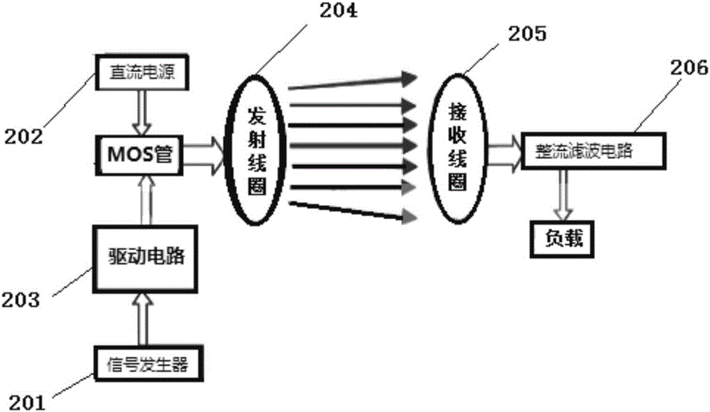
[0033] 1. A set of magnetic resonance coupling wireless power transmission test system independently built, including: signal transmitter 201, DC power supply 202, drive circuit 203 (including power amplifier), transmitting coil 204 and receiving coil 205, rectification and filtering circuit 206 and load ;Such as figure 2 As shown: in this system, the parameters of the transmitting coil 204 and the receiving coil 205 are consistent, the number of turns N of the coils is 20 turns, the diameter is 6.5cm, the Litz wire of 0.01mmx40, the capacitance is 1.5nF, and a corresponding MOS tube, signal transmitter 201, DC power supply 202, etc., the operating frequency of the system is 536kHz, and the DC power supply voltage for the resonant coil is 10V.

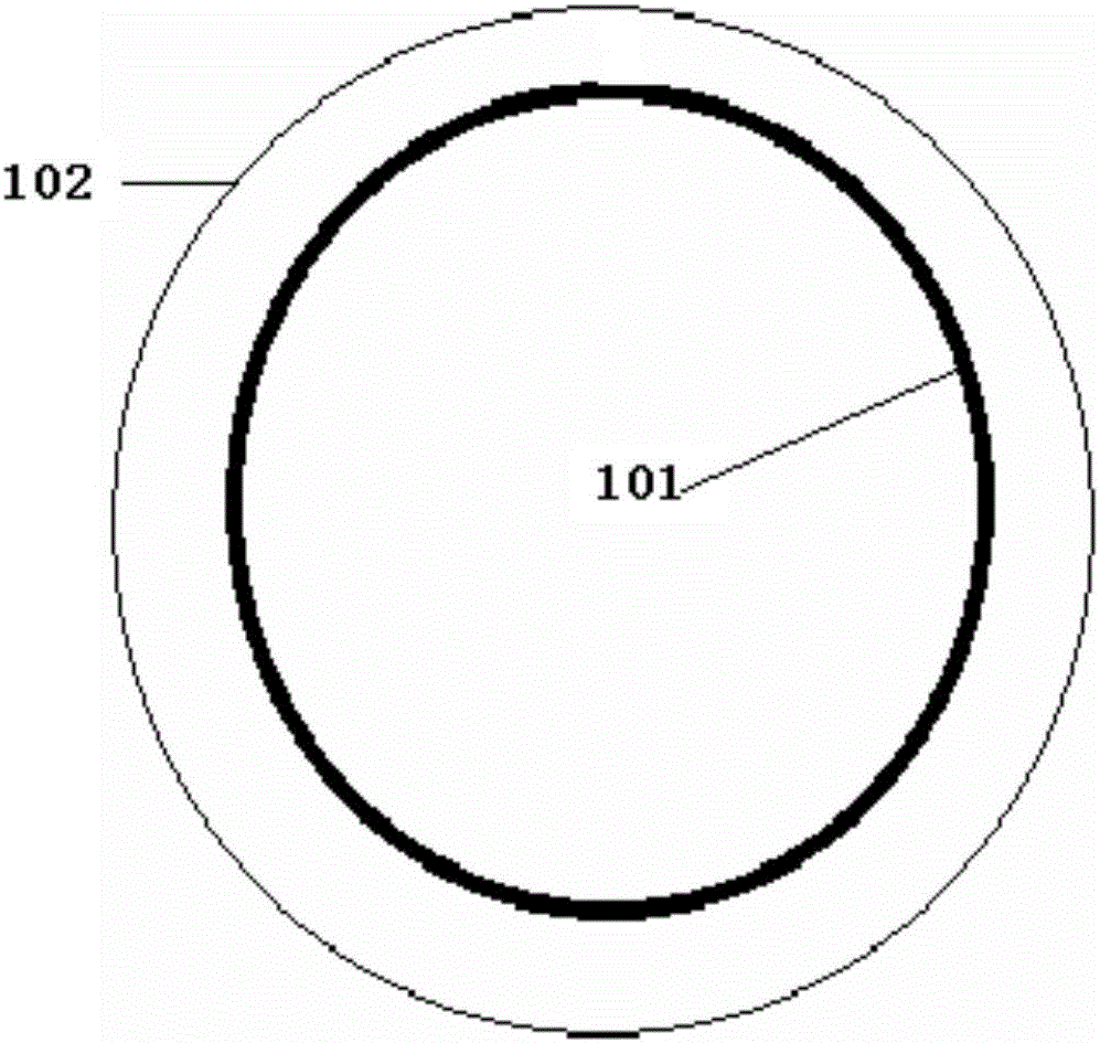
[0034] 2. Based on the above-mentioned magnetic coupling wireless charging system, on the periphery of the transmitter coil, a ring-shaped electromagnetic coil is wound close to the transmitter coil, wrapping the transmitter coil, and...


PUM


Abstract

The invention relates to a magnetic coupling wireless charging device having properties of high efficiency and a high safety factor. The charging device comprises a magnetic coupling wireless charging solenoid and further comprises an annular solenoid arranged outside the magnetic coupling wireless charging solenoid, wherein height of the annular solenoid is not lower than the magnetic coupling wireless charging solenoid, an output power of a compensation power source is quite smaller than a power of a magnetic field power source generated by the magnetic coupling wireless charging solenoid, the annular solenoid can cover a solenoid of a main loop, and a magnetic field direction generated after providing a current to the additional annular solenoid is guaranteed to be opposite to a leakage magnetic field direction at an outer side of the main loop. The charging device is advantaged in that parallel leakage prevention and compensation design concept is employed, so not only can poor safety existing in wireless charging in the prior art be well solved, but also work efficiency of the wireless charging technology is substantially enhanced, and application prospects of the wireless charging technology are improved.

Description

technical field [0001] The invention belongs to the technical field of new energy, in particular to a magnetically coupled wireless charging device with high efficiency and high safety factor. The device has high charging efficiency and high safety factor. Background technique [0002] Wireless charging can make people's life more convenient, and can eliminate problems such as virtual connections, arcs, grid fluctuations, and invalid power consumption that may be caused by power plugging. It has attracted more and more attention in the application fields of mobile phone charging and electric vehicle charging; [0003] Magnetic coupling wireless charging technology is the mainstream technology of wireless charging at present. Reducing magnetic field leakage is the most effective way to improve the efficiency of magnetic coupling wireless charging. In the existing technology, the structural method of adding magnetic isolation sheets to the coil is mostly used to reduce the leak...

Claims


Application Information

Patent Timeline
IPC IPC(8): H02J50/12H02J7/00
CPCH02J7/025
Inventor 薛晨光杨武保陆钧
Owner 伽行科技(北京)有限公司
Why Eureka
Try Eureka