Rooftop photovoltaic power station mounting frame

A technology for installing brackets and photovoltaic power stations, which is applied to the support structure of photovoltaic modules, photovoltaic power generation, photovoltaic modules, etc., can solve the problems of roof structure damage, slow construction progress, and prolonged construction period, and achieve simple construction, easy installation, and low cost. Effects of job safety risks

Pending Publication Date: 2017-04-26
YUEQING JIAOYANG NEW ENERGY TECH CO LTD
View PDF0 Cites 1 Cited by
  • Summary
  • Abstract
  • Description
  • Claims
  • Application Information

AI Technical Summary

Problems solved by technology

The cost of photovoltaic modules and inverters is gradually decreasing, but there are two main ways to install traditional photovoltaic panels. One is to pour concrete cement piers on the roof concrete plane first, and then install metal on the cement piers after the cement piers are dry and solidified. Support the base, and then build a photovoltaic square array. Although the installation is firm in this way, its main disadvantages are 1: the cement pier and the roof are not completely bonded, and the adhesion is not enough
2: It is necessary to wait for the cement pier to dry and solidify before construction, and the construction period will be extended a lot
3: When installing the metal bracket, the horizontal, vertical and height requirements are relatively strict, and the construction progress is relatively slow
Although this installation method is convenient to install, its main disadvantages are 1: Installing expansion screws on the concrete roof will cause damage to the roof structure, and there is a hidden danger of roof leakage
2: When installing the metal bracket, the horizontal, vertical and height requirements are relatively strict, and the construction progress is relatively slow

Method used


Image

  • Rooftop photovoltaic power station mounting frame
  • Rooftop photovoltaic power station mounting frame
  • Rooftop photovoltaic power station mounting frame

Examples


Embodiment Construction

[0018] The following further describes the embodiments of the present invention with reference to the accompanying drawings:

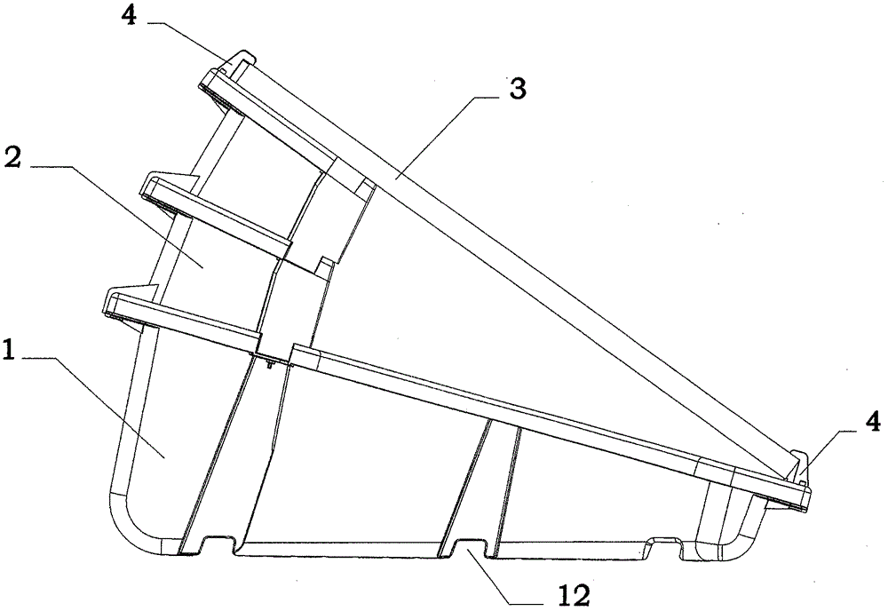
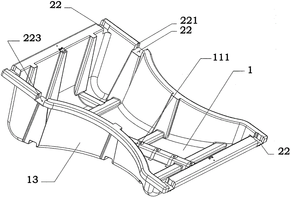
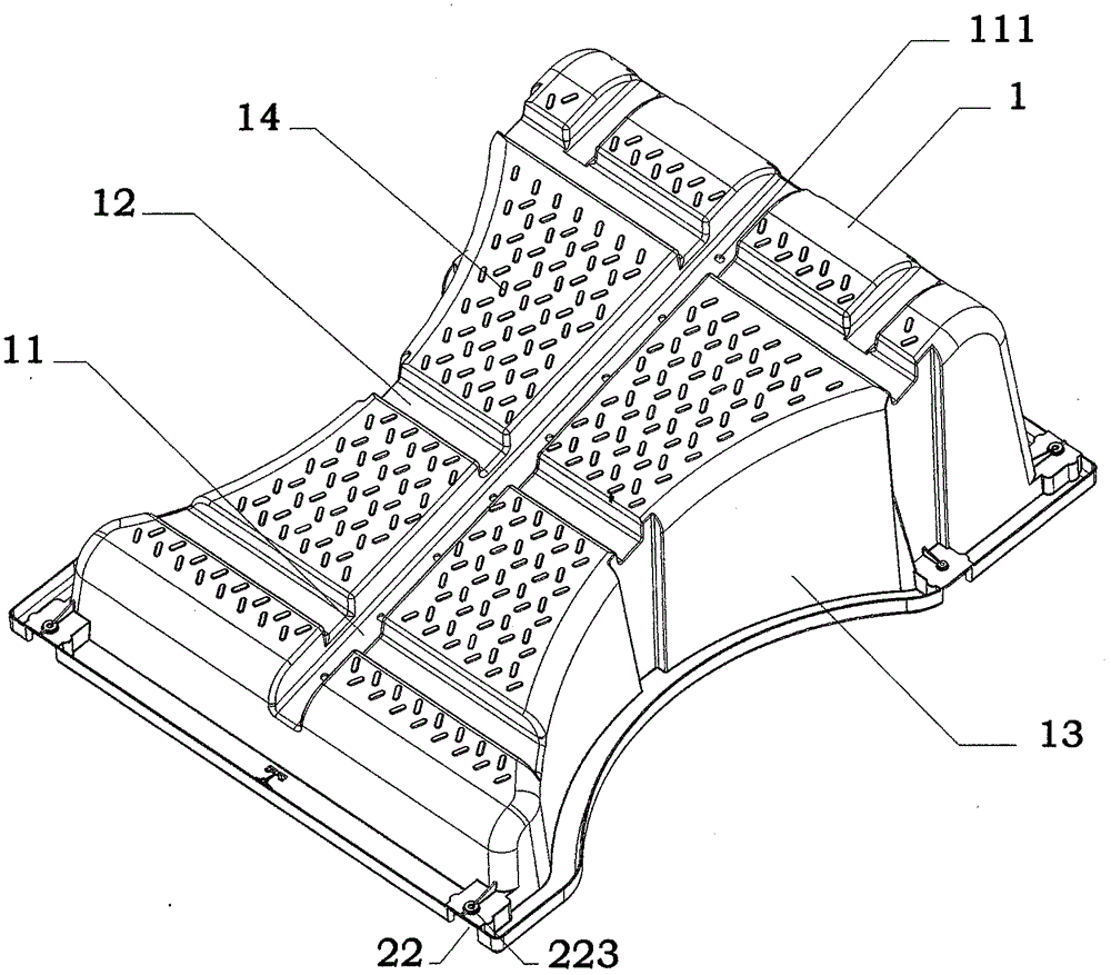
[0019] Such as Figure 1-6 As shown, the present invention is a mounting bracket for a rooftop photovoltaic power station, including a bracket base 1, the upper end surface of the bracket base 1 is an inclined surface and the angle a between the bottom end surface of the bracket base 1 is 15° The bracket base 1 forms high and low ends; an adjusting bracket base 2 is provided on the upper end surface of the high end of the bracket base 1. The upper and lower end surfaces of the adjusting bracket base 3 are arranged at an angle b of 10° and are fixedly connected to the bracket base 1; The plate 3 is connected to the bracket base 1 through two sets of mounting seats 4, which are respectively fixed on both sides of the lower end of the adjusting bracket base 2 and the bracket base 1. A 15° inclined surface is provided on the upper end of the bracket base 1. ...


PUM


Abstract

The invention relates to a rooftop photovoltaic power station mounting frame, which comprises a frame seat. The upper end surface of the frame seat is an oblique surface, the included angle with the bottom end surface of the frame seat is 15 DEG, and thus, a higher end and a lower end of the frame seat are formed; the higher-end upper end surface of the frame seat is provided with an adjustment frame seat, the included angle between the upper end surface and the lower end surface of the adjustment frame seat is 10 DEG, and the adjustment frame seat is fixedly connected with the frame seat; and a photovoltaic panel is connected with the frame seat through two groups of mounting seats. The rooftop photovoltaic power station mounting frame has the beneficial effects that the 15-DEG oblique upper end surface of the frame seat enables the higher end and the lower end of the frame seat to be formed, thereby effectively broadening the use area of mounting frame and enhancing the universality of the mounting frame; and as the adjustment frame seat with the 10-DEG included angle is additionally arranged on the mounting seat, the all-area and all-season use requirements of the mounting frame are mainly improved, the use demands of the rooftop photovoltaic power station in different areas and different seasons are enhanced to the maximum degree, and the power generation efficiency of the rooftop photovoltaic power station can be effectively enhanced.

Description

Technical field [0001] The invention relates to an auxiliary tool, and more specifically to a lowering wheel for assisting the lowering of an enameled wire reel, and is mainly used in the field of enameled wire production. Background technique [0002] As the country's guidance on photovoltaic policies has gradually shifted from the west to the central and eastern regions, the market for photovoltaic power stations on flat roofs in the central and eastern regions is growing. The photovoltaic industry is a new energy industry with great market potential and mature production. Reducing the cost of electricity per kilowatt-hour and achieving parity on the grid is the tireless pursuit of photovoltaic professionals all over the world for the past 60 years, and it is also the pressure of complete marketization. The cost of photovoltaic modules and inverters is gradually decreasing, but there are two main traditional installation methods for photovoltaic panels. One is to pour concrete...

Claims


Application Information

Patent Timeline
Patent Type & Authority Applications(China)
IPC IPC(8): H02S20/30
CPCH02S20/30Y02B10/10Y02E10/50
Inventor 林伟义
Owner YUEQING JIAOYANG NEW ENERGY TECH CO LTD
Why Eureka
Try Eureka