Time stamp generation method and device for a real-time transport protocol system
A technology of real-time transmission protocol and generating device, which is applied in the direction of transmission system, time division multiplexing system, electrical components, etc., and can solve problems such as time stamp jumping
- Summary
- Abstract
- Description
- Claims
- Application Information
AI Technical Summary
Problems solved by technology
Method used
Image
Examples
Embodiment 1
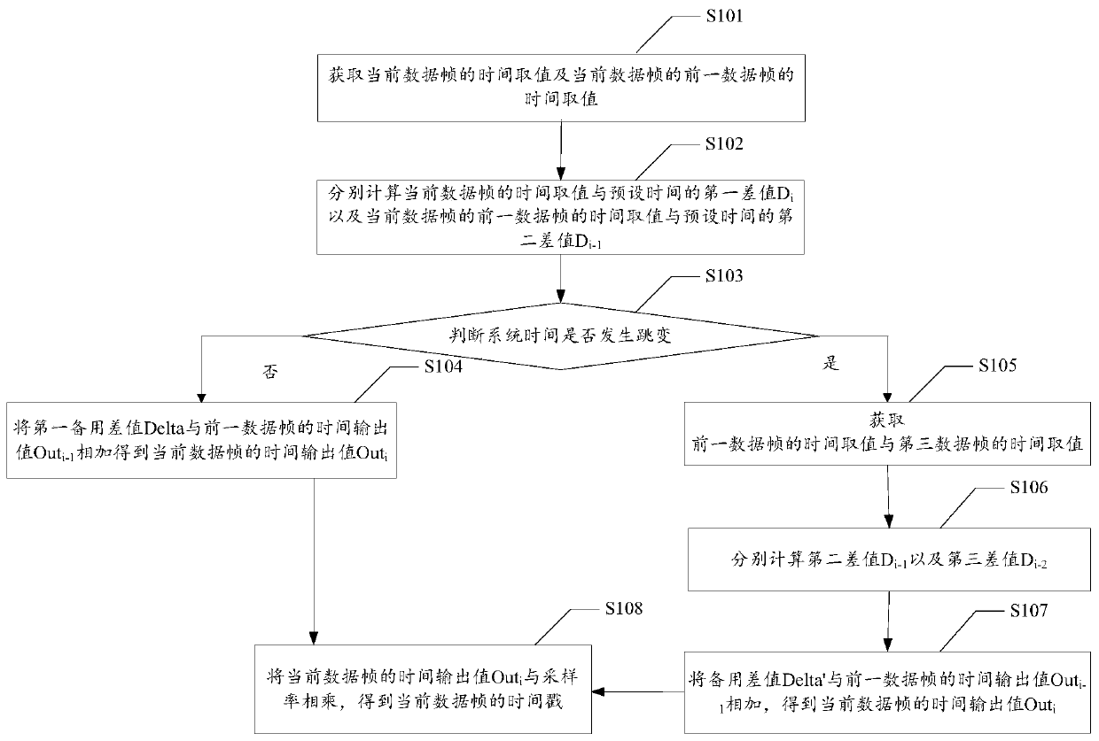
[0016] see figure 1 , figure 1 It is a flow chart of the method of Embodiment 1 of the present application, such as figure 1 As shown, the embodiment of the present application provides a method for generating a time stamp of a real-time transport protocol system, which may specifically include the following steps:
[0017] S101. Obtain the time value of the current data frame and the time value of the previous data frame of the current data frame.
[0018] S102. Calculate the first difference D between the time value of the current data frame and the preset time respectively i And the second difference D between the time value of the previous data frame of the current data frame and the preset time i-1 .
[0019] S103, the absolute value |D according to the magnitude of the difference between the first difference and the second difference i –D i-1 |Determine whether the system time jumps, if not, execute steps S104 and S109, if yes, execute steps S105-S109.
[0020] Th...
Embodiment 2
[0031] An embodiment of the present application provides a method for generating a time stamp of a real-time transport protocol system, which may specifically include the following steps:
[0032] S201. Initially, the video encoder acquires the time difference D between the current time T0 and the preset time Tb while encoding the 0th frame of video data frame 0 , as the time reference point, and output the current time value Out at the same time 0 =D 0 , that is, the time reference point D 0 Time output value Out as initial data frame 0 output.
[0033] The preset time Tb may be, for example, January 1, 1970, which is used in this example for introduction. It can be understood that the preset time is used as a reference time. In this example, the specific time point of the preset time Tb can also be other date and time, such as January 1, 1971, specifically when setting the preset time Tb , the preset time can be taken to the millisecond level according to actual needs a...
Embodiment 3
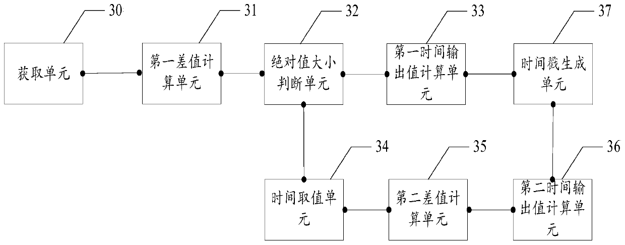
[0059] see figure 2 , figure 2 It is a schematic structural diagram of Embodiment 2 of the present application, such as figure 2 As shown, the embodiment of the present application provides a timestamp generation device for a real-time transport protocol system, which may include:
[0060] The acquiring unit 30 is configured to acquire the time value of the current data frame and the time value of the previous data frame of the current data frame.
[0061] The first difference calculation unit 31 is used to calculate the first difference D between the time value of the current data frame and the preset time, respectively. i And the second difference D between the time value of the previous data frame of the current data frame and the preset time i-1 .
[0062] An absolute value judging unit 32, configured to determine the absolute value |D according to the size of the difference between the first difference and the second difference i –Di-1 |Judge whether the system ti...
PUM
 Abstract
Description
Claims
Application Information
 - R&D
- Intellectual Property
- Life Sciences
- Materials
- Tech Scout
- Unparalleled Data Quality
- Higher Quality Content
- 60% Fewer Hallucinations
Browse by: Latest US Patents, China's latest patents, Technical Efficacy Thesaurus, Application Domain, Technology Topic, Popular Technical Reports.
© 2025 PatSnap. All rights reserved.Legal|Privacy policy|Modern Slavery Act Transparency Statement|Sitemap|About US| Contact US: help@patsnap.com


