Time stamp generating method and time stamp generating device of real-time transmission protocol system

A technology of real-time transmission protocol and generating device, which is applied in the direction of transmission system, time division multiplexing system, electrical components, etc., and can solve problems such as time stamp jumping

Active Publication Date: 2017-04-26
SHENZHEN FANHAI SANJIANG TECH DEV
View PDF6 Cites 8 Cited by
  • Summary
  • Abstract
  • Description
  • Claims
  • Application Information

AI Technical Summary

Problems solved by technology

[0006] This application provides a time stamp generation method and device for a real-time transport protocol system, which can solve the problem of time stamp jumps caused by system time being modified, and reduce time stamp generation errors

Method used


Image

  • Time stamp generating method and time stamp generating device of real-time transmission protocol system
  • Time stamp generating method and time stamp generating device of real-time transmission protocol system
  • Time stamp generating method and time stamp generating device of real-time transmission protocol system

Examples


Embodiment 1

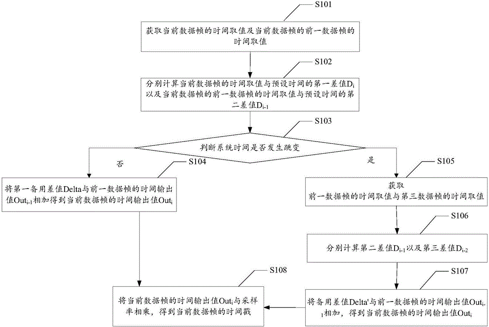
[0016] see figure 1 , figure 1 It is the flow chart of the method of Embodiment 1 of the present application, such as figure 1 As shown, the embodiment of the present application provides a method for generating a time stamp of a real-time transport protocol system, which may specifically include the following steps:

[0017] S101. Obtain the time value of the current data frame and the time value of the previous data frame of the current data frame.

[0018] S102. Calculate the first difference D between the time value of the current data frame and the preset time respectively i And the second difference D between the time value of the previous data frame of the current data frame and the preset time i-1 .

[0019] S103, the absolute value |D according to the magnitude of the difference between the first difference and the second difference i –D i-1 |Determine whether the system time jumps, if not, execute steps S104 and S109, if yes, execute steps S105-S109.

[0020] ...

Embodiment 2

[0031] An embodiment of the present application provides a method for generating a time stamp of a real-time transport protocol system, which may specifically include the following steps:

[0032] S201. Initially, the video encoder acquires the time difference D between the current time T0 and the preset time Tb while encoding the 0th frame of video data frame 0 , as the time reference point, and output the current time value Out at the same time 0 =D 0 , that is, the time reference point D 0 Time output value Out as initial data frame 0 output.

[0033] The preset time Tb may be, for example, January 1, 1970, which is used in this example for introduction. It can be understood that the preset time is used as a reference time. In this example, the specific time point of the preset time Tb can also be other date and time, such as January 1, 1971, specifically when setting the preset time Tb , the preset time can be taken to the millisecond level according to actual needs a...

Embodiment 3

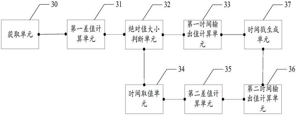
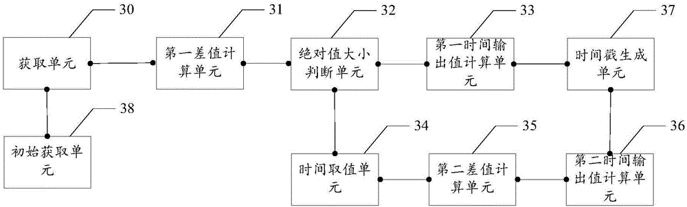
[0059] see figure 2 , figure 2 It is a schematic structural diagram of Embodiment 2 of the present application, such as figure 2 As shown, the embodiment of the present application provides a timestamp generation device for a real-time transport protocol system, which may include:

[0060] The acquiring unit 30 is configured to acquire the time value of the current data frame and the time value of the previous data frame of the current data frame.

[0061] The first difference calculation unit 31 is used to calculate the first difference D between the time value of the current data frame and the preset time, respectively. i And the second difference D between the time value of the previous data frame of the current data frame and the preset time i-1 .

[0062] An absolute value judging unit 32, configured to determine the absolute value |D according to the size of the difference between the first difference and the second difference i –Di-1 |Judge whether the system ti...


PUM


Abstract

The invention discloses a time stamp generating method and a time stamp generating device of a real-time transmission protocol system. When system time is not modified, a time difference between a current time value and a last time value is calculated, and the time difference is added to a last time output value to be used as a current time output value. When time hopping occurs, the time difference is not calculated, and the last time difference is added to the last time output value to be used as the current time output value. A time output value of a current data frame is multiplied by a data sampling rate to acquire the time stamp of the current data frame, and therefore a problem of time stamp hopping caused by the modification of the system time is solved, and the generating error of the time stamp is reduced.

Description

technical field [0001] The present application relates to the field, in particular to a method and device for generating a time stamp of a real-time transport protocol system. Background technique [0002] The timestamp reflects the sampling instant of the first byte of data in the RTP packet. The initial value of the timestamp at the beginning of a session is also randomly selected. Even when no signal is sent, the value of the timestamp will continue to increase over time. Timestamps are used by the receiving end to know exactly which data block should be restored at what time, eliminating jitter in transmission. Timestamps can also be used to synchronize sound and images in video applications. [0003] In the prior art, there are generally two ways to obtain the time stamp. The first method: Randomly generate the timestamp of the initial frame of the video stream, denoted as T0, and calculate the timestamp increment according to the frame rate and video sampling rate....

Claims


Application Information

Patent Timeline
Patent Type & Authority Applications(China)
IPC IPC(8): H04L29/06H04J3/06
CPCH04J3/0661H04L65/65
Inventor 栗楠徐有亮刘平陈建文
Owner SHENZHEN FANHAI SANJIANG TECH DEV
Why Eureka
Try Eureka