Light supplementary component and electronic equipment

A technology of electronic equipment and components, which is applied in the field of light source application, and can solve the problem of insufficient fill light brightness of fill light

Inactive Publication Date: 2017-04-26
VIVO MOBILE COMM CO LTD
View PDF3 Cites 15 Cited by
  • Summary
  • Abstract
  • Description
  • Claims
  • Application Information

AI Technical Summary

Problems solved by technology

[0003] Embodiments of the present invention provide a supplementary light assembly and electronic equipment to solve the problem that the supplementary light brightness of the supplementary light is not enough when the supplementary light and the light outlet are off-centered

Method used


Image

  • Light supplementary component and electronic equipment
  • Light supplementary component and electronic equipment
  • Light supplementary component and electronic equipment

Examples


no. 1 example

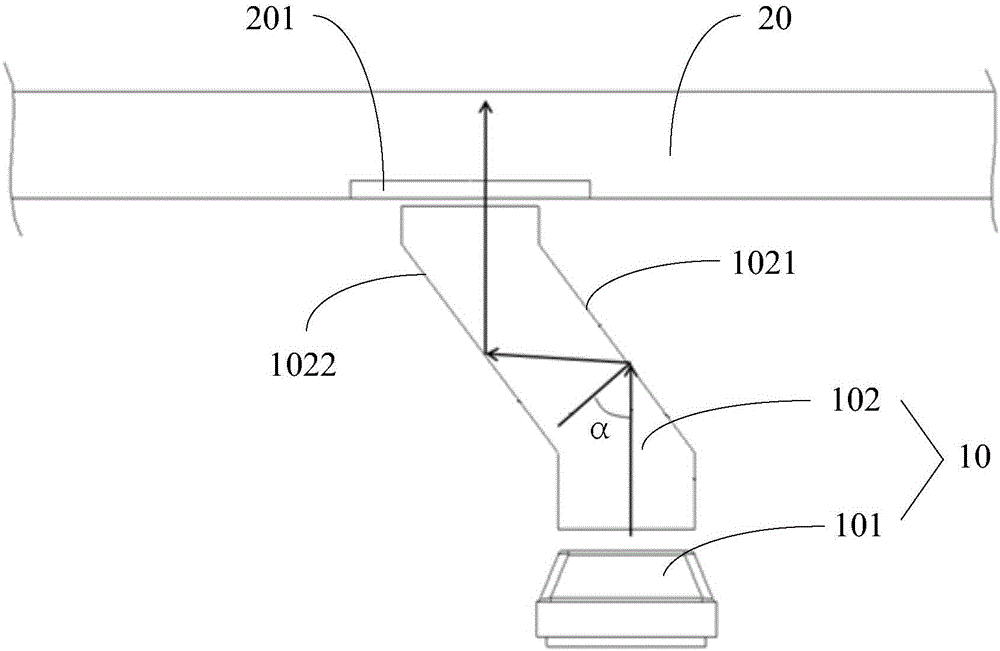
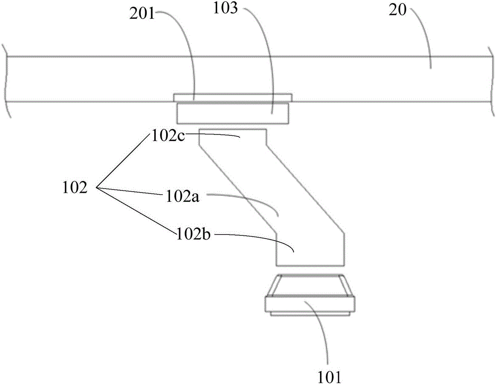
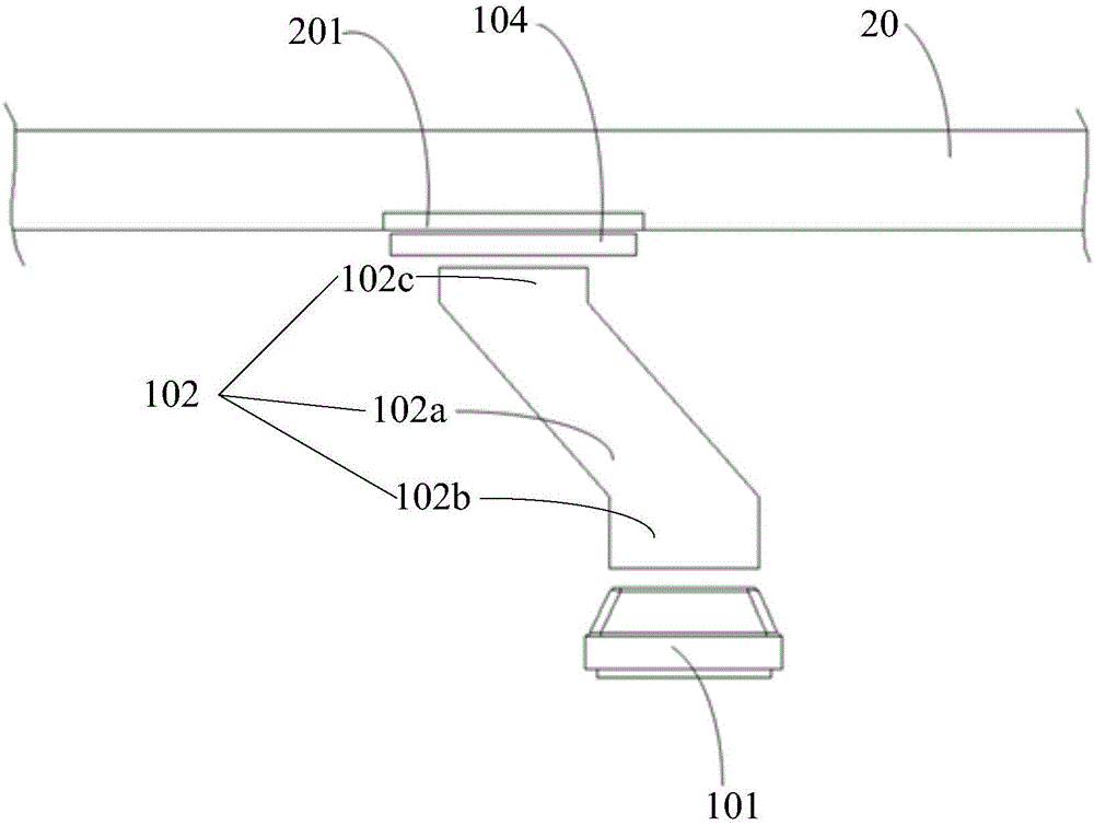
[0016] refer to figure 1 and figure 2 , provides an assembly structure diagram of the supplementary light assembly of the present invention. The supplementary light assembly 10 provided by the embodiment of the present invention is applied to electronic equipment. The supplementary light assembly 10 includes a light source 101 and a light guide column 102. The first end of the light guide column 102 is arranged facing the light source 101, and the second end of the light guide column is directed towards the output light of the electronic device. The hole 201 is set so that the light emitted from the light guide column 102 exits the electronic device through the light exit hole 201, and the light guide column 102 is provided with a first reflective surface 1021 and a second reflective surface 1022;

[0017] The light from the light source 101 enters from the first end of the light guide bar 102 , is reflected by the first reflective surface 1021 and the second reflective surf...

no. 2 example

[0029] see Figure 4 , Figure 4 It is a structural diagram of the electronic equipment provided by the implementation of the present invention.

[0030] Such as Figure 4 As shown, the electronic device 400 includes a radio frequency (Radio Frequency, RF) circuit 410 , a memory 420 , an input unit 430 , a display unit 440 , a processor 450 , an audio circuit 460 , a communication module 470 , a power supply 480 and a supplementary light assembly 490 .

[0031] Optionally, the supplementary light assembly 490 includes a light source and a light guide post, the first end of the light guide post is set facing the light source, and the second end of the light guide post is set facing the light exit hole, so that the light emitted from the light guide post exits the electronic device through the light exit hole, A first reflective surface and a second reflective surface are arranged in the light guide column;

[0032]Wherein, light from the light source enters from the first en...


PUM


Abstract

The present invention provides a light supplementary component and electronic equipment. The light supplementary component comprises a light source and a light guiding column. The first end of the light guiding column faces the light source, the second end of the light guiding column faces the light out hole of the electronic equipment, and thus the light emitted out of the electronic equipment from the light guiding column through the light out hole. The light guiding column is internally provided with a first reflection surface and second reflection surface. The light beam of the light source is emitted into the first end of the light guiding column, and the light beam is emitted out of the second end of the light guiding column after the light beam passes the first reflection surface and the second reflection surface. Since the light guiding column is added between the light source and the light out hole, the light beam emitted by the light source can be emitted out of the light out hole via the light column guide, a problem of insufficient light intensity of the light source caused by the eccentric phenomenon of the light source and the light out hole is solved.

Description

technical field [0001] The invention relates to the technical field of light source applications, in particular to a supplementary light assembly and electronic equipment. Background technique [0002] As we all know, the existing mobile phone is usually equipped with a front camera. In order to meet the demand for supplementary light, a supplementary light is installed near the front camera. The supplementary light is located at the bottom of the touch screen. The light exit hole through which the light of the lamp exits. However, due to the current level of production technology, it is usually easy to cause an eccentric phenomenon between the fill light and the light exit hole, resulting in insufficient fill light brightness of the fill light. Contents of the invention [0003] Embodiments of the present invention provide a supplementary light assembly and electronic equipment to solve the problem that the supplementary light brightness of the supplementary light is ins...

Claims


Application Information

Patent Timeline
Patent Type & Authority Applications(China)
IPC IPC(8): H04M1/02H04M1/22G03B15/05G03B30/00
CPCH04M1/026H04M1/22G03B15/05
Inventor 占智贵刘明建
Owner VIVO MOBILE COMM CO LTD
Why Eureka
Try Eureka