
Nitrogen-feeding mixing device

A stirring device and nitrogen-passing technology, applied in the directions of transportation and packaging, dissolving, mixer, etc., can solve the problems of complicated operation and high cost of electricity, and achieve the effect of uniform stirring and production cost saving.

Inactive Publication Date: 2017-05-03
DONGYING YINQIAO CHEM CO LTD
View PDF0 Cites 1 Cited by
  • Summary
  • Abstract
  • Description
  • Claims
  • Application Information

AI Technical Summary

Problems solved by technology

[0003] According to the deficiencies of the prior art, the present invention provides a nitrogen-flowing stirring device, which solves the problems of complicated operation and high electricity cost of the common stirring method by simultaneously stirring the upper and lower parts of the raw material tank with nitrogen

Method used


Image

  • Nitrogen-feeding mixing device

Examples


Embodiment Construction

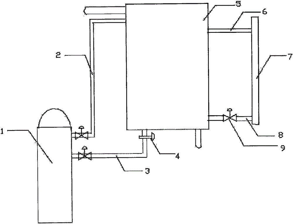
[0010] Reference attached figure 1 , A nitrogen agitating device, comprising: a nitrogen tank 1 and a storage tank 5. Two inlet pipes 2 and 3 are arranged on the upper part of the nitrogen tank 1, and the inlet pipe I 2 and the inlet pipe II 3 are respectively connected to the storage tank At the bottom and upper part of 5, the connection between the inlet pipe II 3 and the bottom of the storage tank 5 is provided with a check valve 4 to prevent the liquid in the storage tank from flowing back into the inlet pipe II 3. Two connections are provided on the other side of the storage tank 5. There is a connecting pipe I 6 and a connecting pipe II 8 with a liquid level gauge 7, and the air inlet pipe I 2 and the air inlet pipe II 3 are both provided with a control valve 9. The upper connecting pipe I 6 has no control valve, and the lower connecting pipe II 8 is equipped with a control valve 9.


PUM


Abstract

The invention discloses a nitrogen-feeding mixing device. Compared with the traditional mixing device, the nitrogen-feeding mixing device has outstanding features of operation simpleness and low cost. The technical scheme comprises that two nitrogen feeding pipes are connected to the upper part of a nitrogen tank, the bottom and the top of a storage tank are respectively connected to the nitrogen feeding pipes, the joint of the nitrogen inlet pipe II and the storage tank is provided with a check valve for preventing the liquid in the storage tank from flowing back into the nitrogen pipe II, at one side of the storage tank, an upper connection pipe and a lower connection pipe are connected to a liquidometer, the nitrogen pipes are provided with control valves, according to demands, the nitrogen feeding situation is controlled, the lower connection pipe is provided with a control valve, and the upper connection pipe has no a control valve. The nitrogen-feeding mixing device improves the accuracy of the operation.

Description

Technical field [0001] The invention relates to the technical field of chemical equipment, in particular to a nitrogen-passing stirring device. Background technique [0002] In the later stage of the chemical production process, the materials enter the storage tank after distillation, and the product is obtained after inspection. In the storage tank, it needs to be tested whether it meets the requirements. At this time, to ensure the uniformity of the tested product, it needs to be stirred. The stirring devices are all set at the bottom of the tank, and it takes a long time to stir to achieve better results. Moreover, the currently used stirring devices are all driven by a motor, which consumes a lot of power, especially in the case of low temperature. It also takes a long time to stir to achieve better results. When operating in a reactor with an electric heating rod, although the stirring time can be shortened, the electricity consumption is also very large, and the electricity...

Claims


Application Information

Patent Timeline
IPC IPC(8): B01F13/02B01F33/40
Inventor 李广义张连海
Owner DONGYING YINQIAO CHEM CO LTD
Learn More