Dish-washing machine spray thrower, dish-washing machine provided with the spray thrower and control method

A control method and technology for dishwashers, which are applied to dishwashers/washing machines for tableware, parts of dishwashers/rinsing machines for tableware, household cleaning devices, etc. The position of the sprinkler is uncontrollable, etc., to achieve the effect of remarkable effect, simple structure and suitable for popularization and use.

Inactive Publication Date: 2017-05-10
QINGDAO HAIER DISHWASHER
View PDF5 Cites 23 Cited by
  • Summary
  • Abstract
  • Description
  • Claims
  • Application Information

AI Technical Summary

Problems solved by technology

[0005] Since the sprinkler of the above-mentioned dishwasher only sprays part of the incoming water to the items placed on the shelf, the water utilization rate is low; and the effective spraying water per unit time is less, requiring a longer washing time To meet the washing cleanliness
[0006] At the same time, since the shower is driven and rotated by the reverse force of the spray water, the position of the shower is uncontrollable, and it is impossible to wash a specific area in the dishwasher.
This makes the user need to spray water on the whole area when placing a small amount of items in some areas, which reduces the washing rate and causes the loss of water resources

Method used


Image

  • Dish-washing machine spray thrower, dish-washing machine provided with the spray thrower and control method
  • Dish-washing machine spray thrower, dish-washing machine provided with the spray thrower and control method
  • Dish-washing machine spray thrower, dish-washing machine provided with the spray thrower and control method

Examples


Embodiment 1

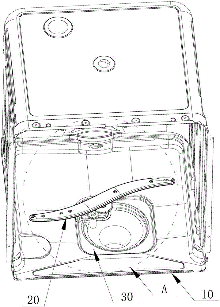
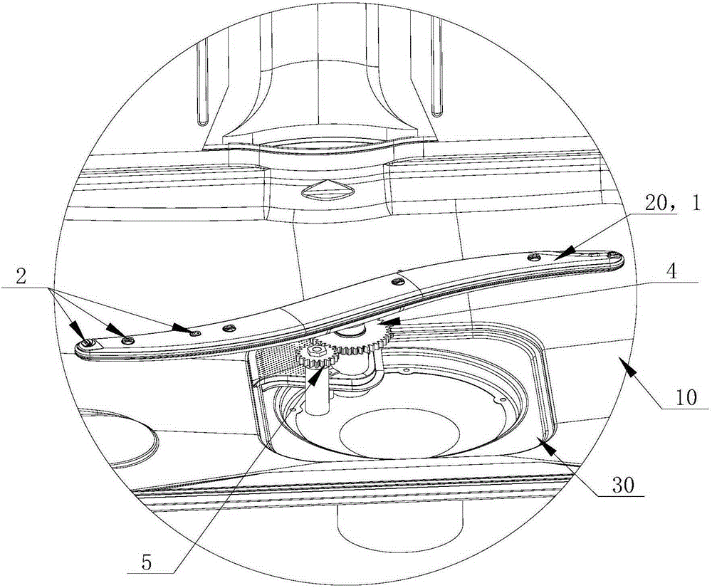
[0049] Such as Figure 1 to Figure 4 As shown, in this embodiment, a sink 30 for discharging washing water is provided at the center of the lower part of the inner container 10 of the dishwasher, and the shower 20 is disposed at the sink 30 . The spray arm 1 of the shower 20 is installed above the sink 30 of the dishwasher, and the motor 3 is arranged below the sink 30 . The motor shaft 31 of the motor 3 passes through the water tank 30 and engages with the rotating shaft 11 of the spray arm 1 on the other side; The motor shaft 31 is meshingly connected. Through the above arrangement, the connection between the motor shaft 31 and the rotating shaft 11 is ensured, so that the motor 3 drives the spray arm 1 to rotate;

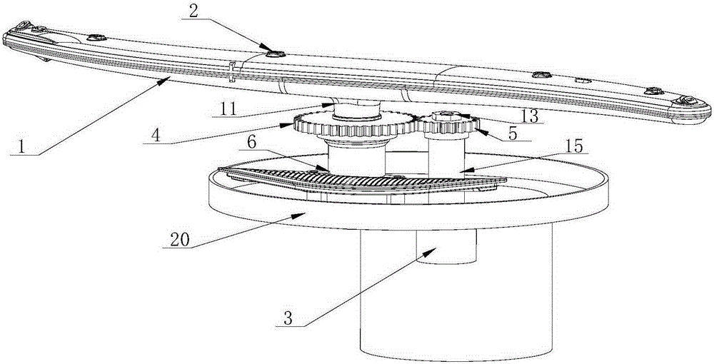
[0050] Such as Figure 4 As shown, in this embodiment, the first gear 4 is fixedly installed on the rotating shaft 11 of the spray arm 1, and the second gear 5 is fixedly installed on the motor shaft 31 of the motor 3; The two gears 5 are meshed for transmiss...

Embodiment 2

[0059] The difference between this embodiment and the first embodiment above is that a sealing device is provided at the place where the motor shaft 31 and / or the rotating shaft 11 passes through the water tank 30, so as to prevent the water from passing through the water tank under the premise of ensuring the rotation of the motor shaft and / or the rotating shaft. Outflow everywhere.

[0060] Such as Figure 5 As shown, in this embodiment, the motor shaft 31 passes through the through hole 9 on the water tank 30 , and the through hole 9 is provided with a waterproof shaft seal 12 for fixing the motor shaft 31 . The waterproof shaft seal 12 is made of elastic rubber material; and the outer circumference of the waterproof shaft seal 12 is in sealing contact with the through hole 9 , and the inner circumference is in sealing contact with the motor shaft 31 .

[0061] Through the above-mentioned arrangement, it is also possible to prevent the water in the water tank from flowing ...

Embodiment 3

[0063] The difference between this embodiment and the first embodiment above is that: the rotating shaft 11 of the spray arm 1 is directly engaged with the motor shaft 31 of the motor 3 , so that the spray arm 1 is driven by the motor 3 to rotate around the rotating shaft 11 .

[0064] Such as Figure 6 As shown, in this embodiment, the motor 3 is arranged at the lower part of the water tank 30 , the spray arm 1 is arranged at the upper part of the water tank 30 , and the rotating shaft 11 of the spray arm 1 is coaxially arranged with the motor shaft 31 of the motor 3 . The motor shaft 31 of the motor 3 passes through the water tank 30 from top to bottom, and is directly fixedly connected with the rotating shaft 11 . The fixed connection mode between the motor shaft 31 and the rotating shaft 11 can be any fixed connection mode in the prior art, such as: threaded connection, buckle connection, shaft sleeve connection, key connection, etc.; Figure 6 In the shown manner, the up...


PUM


Abstract

The invention relates to a dish-washing machine spray thrower. The dish-washing machine spray thrower comprises a spray arm arranged horizontally, at least one spray hole is formed in the spray arm, the spray arm is connected with a motor in a meshed mode directly or through a transmission mechanism, and driven by the motor, and the spray arm rotates or sways in the horizontal plane. The invention further provides a dish-washing machine provided with the spray thrower and a control method. Driven by the motor, the spray arm sways back and forth at a certain angle and therefore the sprayed water radiates to the whole or part area of the dishing-washing machine and articles in the area are washed. Thus, the sprayed water flow does not need to be used for driving the spray arm to rotate and is all used for washing the articles to reduce water consumption; at the same time, the spray arm conducts swaying back and forth in a certain area and achieves the purpose of reinforced washing or specific washing for the certain area and fulfills the purpose of increasing the washing efficiency of the washing machine. Meanwhile, the dish-washing machine spray thrower and the dish-washing machine provided with the spray thrower are simple in structure, obvious in effect and suitable for popularization and use.

Description

technical field [0001] The present invention relates to a dishwasher in the field of household appliances, in particular to a shower of the dishwasher, and also to a control method for the dishwasher using the shower. Background technique [0002] Dishwashers are household appliances used to automatically wash tableware. With the continuous improvement of people's living standards, the application of dishwashers has become more and more extensive. In order to ensure the market competitiveness of dishwashers, relevant technical personnel are Research on how to continuously improve the overall performance of dishwashers. [0003] The washing process of existing household dishwashers is generally as follows: the washing water enters the shower from the water outlet of the water diversion valve through the washing pump, and the high-pressure water is sprayed out along the nozzles arranged on the surface of the shower to clean the inner tank. Placed items for cleaning. [0004]...

Claims


Application Information

Patent Timeline
Patent Type & Authority Applications(China)
IPC IPC(8): A47L15/42A47L15/22
Inventor 姜战存潘显杰李迎
Owner QINGDAO HAIER DISHWASHER
Why Eureka
Try Eureka