
Horizontal spiral centrifugal machine

A decanter centrifuge and screw propeller technology, which is applied in the field of centrifuges, can solve the problems of difficult sediment dehydration and baffle damage, and achieve the effect of not being easily damaged

Inactive Publication Date: 2017-05-10
SUZHOU RUIWEI CENTRIFUGAL SEPARATION TECH
View PDF13 Cites 3 Cited by
  • Summary
  • Abstract
  • Description
  • Claims
  • Application Information

AI Technical Summary

Problems solved by technology

[0005] And because the viscosity of the sediment is relatively high when the sediment is transported to the cone screw section, when the sediment is forced to separate by the baffle, the sediment will give a considerable extrusion force to the baffle, and over time, it is easy to The baffle plate will be damaged, and the sediment layer close to the drum can quickly pass through the gap between the baffle plate and the drum, while the sediment far away from the drum can hardly pass through the gap between the baffle plate and the drum. Since the sediment at the side of the sediment layer away from the drum is often in contact with the liquid phase, the sediment on the side away from the drum contains the most liquid phase, while the sediment at the side of the sediment layer near the drum is subjected to The centrifugal force is the largest, and the degree of extrusion is also the largest. From this, it can be concluded that the sediment closer to the liquid phase needs to be squeezed and dehydrated, and the current decanter centrifuge is working. , it is difficult to complete the dehydration of this part of the sediment

Method used


Image

  • Horizontal spiral centrifugal machine
  • Horizontal spiral centrifugal machine
  • Horizontal spiral centrifugal machine

Examples

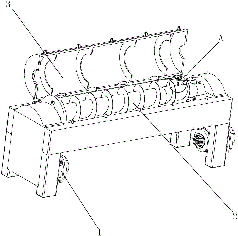

Embodiment Construction

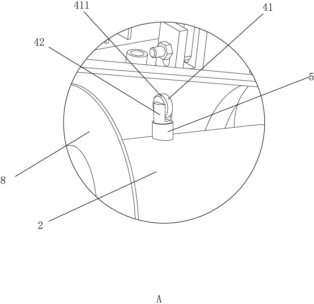
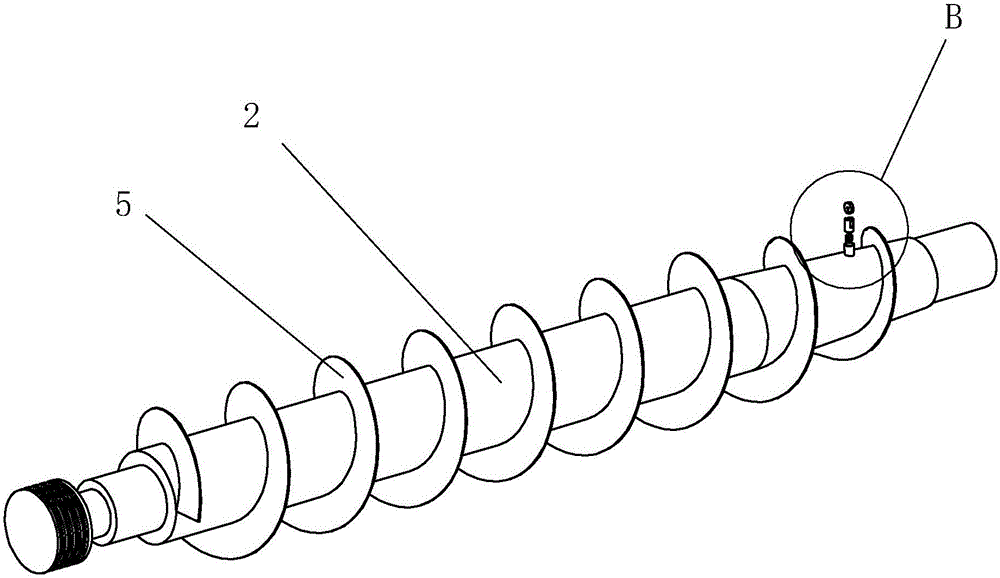
[0026] refer to Figure 1 to Figure 7 The embodiment of a decanter centrifuge of the present invention will be further described.

[0027] A decanter centrifuge, comprising a driving device 1, a drum 3, a screw propeller 2 and a casing, the driving device 1 drives the screw propeller 2 to rotate, the rotating drum 3 is arranged in the casing, and the two ends of the rotating drum 3 are respectively arranged There is a liquid phase outlet and a sediment outlet. The screw propeller 2 is arranged inside the drum 3 and a material pool is formed between the inner wall of the drum 3 and the screw propeller 2. During the working process of the decanter centrifuge, the driving device 1 will drive The screw propeller 2 works, and there will be a power device in addition, and the power device drives the rotating drum 3 to rotate. Since the screw propeller 2 is provided with blades 8, the sediment and the liquid phase are separated by the rotation of the rotating drum 3, and then Throug...


PUM


Abstract

The invention discloses a horizontal spiral centrifugal machine. The horizontal spiral centrifugal machine comprises a driving device, a rotating drum, a spiral propeller and a housing; the driving device drives the spiral propeller to rotate; the rotating drum is arranged in the housing; the two ends of the rotating drum are provided with a liquid phase matter outlet and a sediment outlet; the spiral propeller is arranged in the rotating drum, and a material pond is formed between the inner wall of the rotating drum and the spiral propeller; the side, close to the sediment outlet, of the spiral propeller is provided with a rolling grinding and pressing device performing rolling grinding and pressing on a sediment layer; an elastic piece is arranged between the rolling grinding and pressing device and the spiral propeller; the rolling grinding and pressing device is connected with the spiral propeller through the elastic piece; and by means of the rolling grinding and pressing device, a grinding and pressing effect can be effectively performed on sediment, and the sediment is effectively separated from the liquid phase matter.

Description

technical field [0001] The present invention relates to a centrifuge, more particularly, it relates to a decanter centrifuge. Background technique [0002] Decanter centrifuge is a horizontal spiral unloading, continuous operation settling equipment. The working principle of this type of centrifuge is: the drum and the screw rotate at a high speed in the same direction at a certain differential speed, the material is continuously introduced into the inner cylinder of the feeding screw from the feed pipe, and enters the drum after acceleration. Under the action of the centrifugal force field, the heavier solid The phase deposits on the drum wall to form a sediment layer. The conveying screw continuously pushes the deposited solid phase to the cone end of the drum, and is discharged out of the machine through the slag discharge port. The lighter liquid phase forms an inner liquid ring, continuously overflows the drum from the overflow port at the large end of the drum, and i...

Claims


Application Information

Patent Timeline
Patent Type & Authority Applications(China)
IPC IPC(8): B04B1/20B04B15/00B30B9/20
Inventor 王亚洲
Owner SUZHOU RUIWEI CENTRIFUGAL SEPARATION TECH
Learn More