
Machining method for bulged cavity part

A processing method and cavity technology, which are applied in metal processing equipment, manufacturing tools, turning equipment, etc., can solve the problems of no tooling, turning, and the difficulty of bulging inner cavity parts with large steps, and achieve the effect of convenient operation and simple structure.

Active Publication Date: 2017-05-10
MCC SFRE HEAVY IND EQUIP
View PDF7 Cites 5 Cited by
  • Summary
  • Abstract
  • Description
  • Claims
  • Application Information

AI Technical Summary

Problems solved by technology

[0004] The purpose of the present invention is to provide a processing method for the inner cavity parts of the bulge, which solves the problem that there is no suitable tooling in the prior art, and it is difficult to effectively turn the inner cavity parts of the large step bulge.

Method used


Image

  • Machining method for bulged cavity part
  • Machining method for bulged cavity part
  • Machining method for bulged cavity part

Examples


Embodiment Construction

[0024] The present invention will be described in detail below in conjunction with the accompanying drawings and specific embodiments.

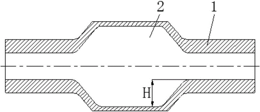
[0025] refer to figure 1 , is the cross-sectional structure of the large step bulging inner cavity part 1 of the processing object of the present invention. On the large step bulging inner cavity part 1, the bulging inner hole 2 needs to be processed, and the step size H of the bulging inner hole 2 is greater than 100mm. In the process of processing, the rigidity and convenience of access of the tooling into the large-step bulging inner cavity part 1 should be ensured, and the turning of the bulging inner hole 2 should be completed.

[0026] The tooling structure adopted by the method of the present invention is to include a bent type inner hole turning tool holder and a clip, and the two are matched together to complete the turning of the processing object.

[0027] refer to figure 2 , image 3 , Figure 4 , Figure 5 , Image 6 , ...


PUM


Abstract

The invention discloses a machining method for a bulged cavity part. The machining method comprises the following steps: (1) clamping a round toolbar in a clamp hole, and firmly mounting a mounting handle on a tool rest of a horizontal lathe; (2) mounting and clamping a big-step bulged cavity part on the horizontal lathe and well aligning; (3) dismounting a nut, and propelling a long bolt into the inner hole of the round toolbar, wherein the long bolt sequentially drives a slider and a connecting plate to advance, so that a longitudinal toolbar and the round toolbar are longitudinally parallel, and through translation of the tool rest, a bent inner hole turning toolbar enters the inner hole of the big-step bulged cavity part; and then backing the long bolt to enable the longitudinal toolbar and the round toolbar to be longitudinally perpendicular, tightening the nut, and fixing the long bolt in the longitudinal direction; and (4) starting up the horizontal lathe, through translation of the tool rest, enabling a turning tool of the bent inner hole turning toolbar to move onto the inner surface of the bulged inner hole of the big-step bulged cavity part, performing tool setting, and then feeding for turning. The machining method is simple in tool and convenient to operate.

Description

technical field [0001] The invention belongs to the technical field of mechanical equipment manufacturing, and relates to a processing method of a bulging inner cavity part. Background technique [0002] In equipment such as large generators, there is a hollow shaft part with a large step and a bulging inner cavity, such as figure 1 As shown, because it needs to run at high speed during the working process, it has extremely high requirements on strength and dynamic balance, so the inner cavity of the bulge is usually machined from a whole material, and it is compatible with the assembled and welded structures. In comparison, the hollow shaft of the integral bulging inner cavity also enhances the reliability of equipment operation. However, the common cavity turning method can only process the cavity with a small step, and cannot process the bulging cavity with a step size H greater than 100 mm. [0003] Therefore, developing a processing device and method for (big steps) b...

Claims


Application Information

Patent Timeline
Patent Type & Authority Applications(China)
IPC IPC(8): B23B5/00
CPCB23B5/00
Inventor 徐卫红
Owner MCC SFRE HEAVY IND EQUIP
Learn More