
Permanent magnet motor driven vertical lathe

A permanent magnet motor and vertical lathe technology, applied in the field of CNC machine tools, can solve problems such as low machining accuracy, high energy consumption, and complicated operation, and achieve the effects of improving stability, convenient maintenance, and reducing power consumption

Pending Publication Date: 2019-12-13
大连宝锋机器制造有限公司
View PDF0 Cites 0 Cited by
  • Summary
  • Abstract
  • Description
  • Claims
  • Application Information

AI Technical Summary

Problems solved by technology

[0003] Traditional vertical lathes are usually complex in structure, large in size and high in energy consumption
And the operation is complicated, the machining accuracy is low, and it cannot meet the requirements of precision parts processing

Method used


Image

  • Permanent magnet motor driven vertical lathe
  • Permanent magnet motor driven vertical lathe

Examples


Embodiment Construction

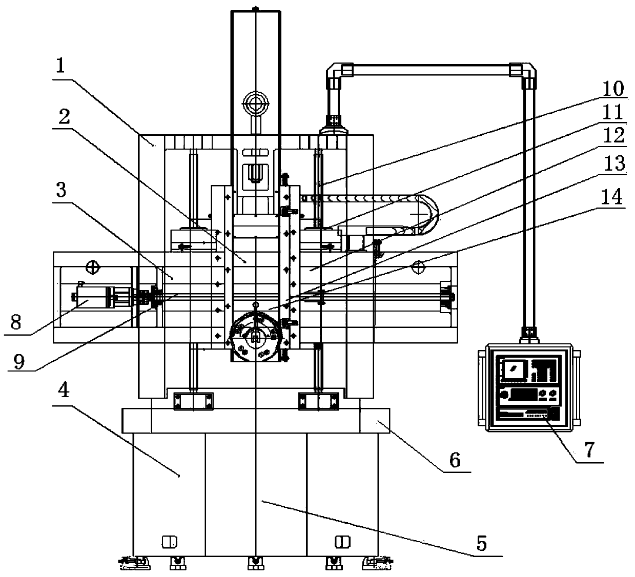
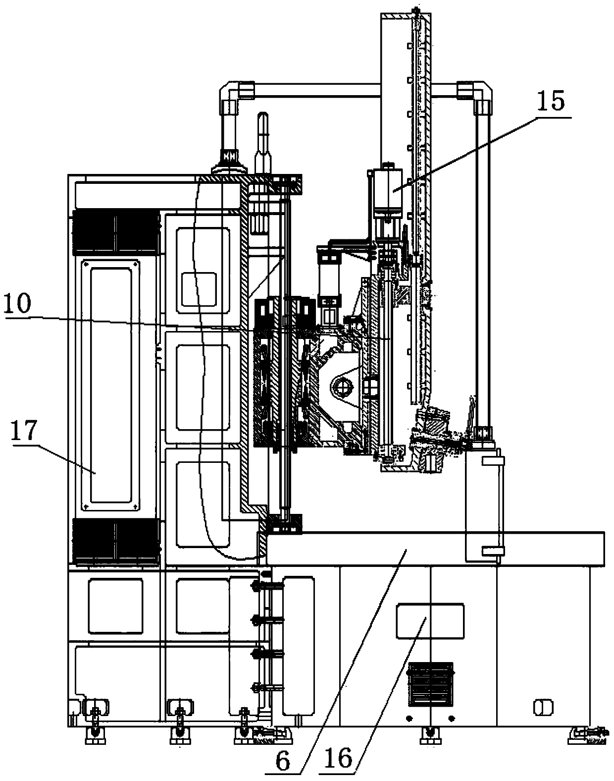
[0013] The structure of a permanent magnet motor driven vertical lathe of the present invention is as follows: figure 1 and figure 2 As shown, the bed 1 is installed on the upper part of the base 4, and the workbench 6 is installed on the upper part of the base 4 at the front of the bed 1. The workbench 6 is connected to the permanent magnet motor 8 located in the base 4. Installed coaxially with the workbench 6, the encoder 16 is directly connected coaxially with the workbench 6 at 1:1; the front side of the bed 1 is provided with a guide rail, and the front side of the bed 1 slides to install the beam 3 through the guide rail, and the rear side of the beam 3 is connected to lift Lead screw 10, lifting screw 10 is connected with vertical servo motor 15; beam slide seat 12 is installed on the front side of cross beam 3, and cross beam slide seat 12 is connected with horizontal servo motor 8 through horizontal lead screw 9, and vertical tool holder is installed at the front of...


PUM


Abstract

The invention provides a permanent magnet motor driven vertical lathe. A lathe bed is mounted on the upper portion of a base. A workbench is mounted in the position, located on the front portion of the lathe bed, of the upper portion of the base. The workbench is connected with a permanent magnet motor located in the base. An encoder is mounted on the workbench. The encoder and the workbench are coaxially mounted. The front side of the lathe bed is provided with guide rails. A cross beam is slidably mounted on the front side of the lathe bed through the guide rails. A lifting lead screw is connected to the rear side of the cross beam. The lifting lead screw is connected with a vertical servo motor. A cross beam sliding seat is slidably mounted on the front side of the cross beam. The crossbeam sliding seat is connected with a horizontal servo motor through a horizontal lead screw. A vertical tool post is mounted on the front portion of the cross beam sliding seat. A ram is mounted onthe lower portion of the vertical tool post through a rotary sliding seat. According to the permanent magnet motor driven vertical lathe, the workbench is provided with the eight-speed permanent magnet motor and can realize stepless speed regulation; the permanent magnet motor driven vertical lathe is compact in structure and low in energy consumption, realizes turning of high-precision threads through the encoder arranged on the workbench; the cross beam is driven to do horizontal and vertical motion through the permanent magnet motor; the stability of the permanent magnet motor driven vertical lathe is improved, and power consumption of the permanent magnet motor driven vertical lathe is reduced; and the permanent magnet motor driven vertical lathe is convenient and easy to maintain.

Description

technical field [0001] The invention relates to the technical field of numerical control machine tools. Background technique [0002] Vertical lathes are large-scale mechanical equipment used to process large and heavy workpieces with large radial dimensions and relatively small axial dimensions and complex shapes. Such as the cylindrical surface, end surface, conical surface, cylindrical hole, conical hole, etc. of various discs, wheels and sleeves. It can also be used for threading, spherical turning, profiling, milling and grinding with the help of additional devices. Generally, it can be divided into single-column and double-column. [0003] Traditional vertical lathes usually have complex structures, large volumes, and high energy consumption. Moreover, the operation is complicated and the processing accuracy is low, which cannot meet the requirements of precision parts processing. Contents of the invention [0004] In order to solve the above-mentioned problems ex...

Claims


Application Information

Patent Timeline
IPC IPC(8): B23Q5/28B23G1/44B23Q1/25
CPCB23Q5/28B23G1/44B23Q1/25
Inventor 贾先义范传良
Owner 大连宝锋机器制造有限公司
Learn More