Multifunctional machining center

A machining center and multi-functional technology, which is applied in the direction of manufacturing tools and other manufacturing equipment/tools, etc., can solve the problems of restricting the functions of machining centers and single functions of machining centers, and achieve high machining accuracy, diversified functions, and high transmission accuracy. Effect

Inactive Publication Date: 2020-03-27
淄博海纳百川机械有限公司
View PDF0 Cites 0 Cited by
  • Summary
  • Abstract
  • Description
  • Claims
  • Application Information

AI Technical Summary

Problems solved by technology

The existing machining center drives the tool to rotate through the spindle, and then realizes the relative rotation between the tool and the workpiece to process the workpiece. This leads to the relatively single function of the existing machining center, which can only perform milling, which greatly limits the processing The function of the center

Method used


Image

  • Multifunctional machining center
  • Multifunctional machining center
  • Multifunctional machining center

Examples


Embodiment Construction

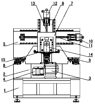
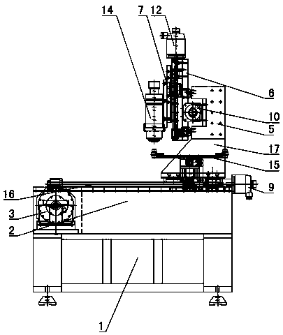
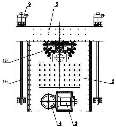
[0029] Figure 1~9 It is the best embodiment of the present invention, below in conjunction with attached Figure 1~9 The present invention will be further described.

[0030] A multifunctional machining center, comprising a traveling mechanism, an electric spindle 14 and a movable worktable, the traveling mechanism is connected with the electric spindle 14 and drives the electric spindle 14 to move, the electric spindle 14 is arranged vertically, and the movable workbench is arranged on the lower side of the electric spindle 14 , the movable workbench is connected with a B-axis power device that drives it to rotate around the vertical shaft, the lower side of the electric spindle 14 is also provided with a tool magazine 15, and the electric spindle 14 is also connected with a self-locking mechanism; the self-locking mechanism includes a locking disc 28. Brake belt and locking power device. The locking disc 28 is coaxially sleeved on the rotor of the electric spindle 14 and r...


PUM


Abstract

The invention discloses a multifunctional machining center, which belongs to the technical field of machining tools. The multifunctional machining center is characterized in that a walking mechanism is connected with an electric spindle (14) and drives the electric spindle (14) to move, the electric spindle (14) is vertically arranged, a movable workbench is arranged on the lower side of the electric spindle (14), the movable workbench is connected with a B-axis power device driving the movable workbench to rotate around a vertical rotating shaft, and the electric spindle (14) is further connected with a self-locking mechanism; the self-locking mechanism comprises a locking disc (28), a brake belt and a locking power device, the locking disc (28) is coaxially arranged on a rotor of the electric spindle (14) in a sleeving mode and synchronously rotates along with the rotor, the brake belt is arranged around the locking disc (28), and the locking power device is connected with the brakebelt and enables the brake belt to clasp or loosen the locking disc (28). The locking disc of the multifunctional machining center is coaxially installed on the rotor of the electric spindle, the locking disc is locked through the brake belt, self-locking is achieved, self-locking is reliable, the structure is simple, and damage is not likely to happen.

Description

technical field [0001] A multifunctional machining center belongs to the technical field of machining tools. Background technique [0002] CNC milling machine is an automatic processing equipment developed on the basis of general milling machine. The processing technology of the two is basically the same, and the structure is somewhat similar. CNC milling machines are divided into two categories without tool magazine and with tool magazine. Among them, the CNC milling machine with tool magazine is also called machining center. The existing machining center drives the tool to rotate through the spindle, and then realizes the relative rotation between the tool and the workpiece to process the workpiece. This leads to the relatively single function of the existing machining center, which can only perform milling, which greatly limits the processing Center function. Contents of the invention [0003] The technical problem to be solved by the present invention is to overcome...

Claims


Application Information

Patent Timeline
Patent Type & Authority Applications(China)
IPC IPC(8): B23P23/02
CPCB23P23/02
Inventor 岳洪庆
Owner 淄博海纳百川机械有限公司
Why Eureka
Try Eureka