
Lathe capable of automatically clamping cutter
A tool and automatic technology, applied in the field of lathes, can solve problems such as low efficiency, inconvenient cleaning, and inability to achieve workpiece grinding, etc., to save time and improve work efficiency.
- Summary
- Abstract
- Description
- Claims
- Application Information
AI Technical Summary
Problems solved by technology
Method used
Image

Examples
Embodiment Construction
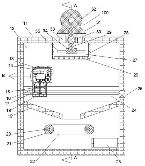
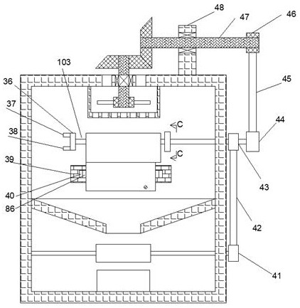
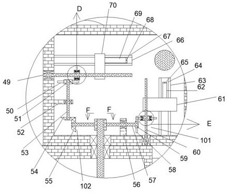
[0019] Combine below Figure 1-7 The present invention is described in detail, wherein, for the convenience of description, the orientations mentioned below are defined as follows: figure 1 The up, down, left, right, front and back directions of the projection relationship itself are the same.
[0020] combined with Figure 1-7The lathe that can automatically clamp tools includes the box body 11 and the first cavity 12 provided in the box body 11, and the upper side end wall of the first cavity 12 is fixedly installed with a fan. The box body 28, the fan installation box box body 28 is provided with a second cavity 27, and the array on the lower end wall of the second cavity 27 is fixed with an air outlet 26, and the second cavity 27 A turntable shaft 29 is rotatably installed on the upper end wall, and the turntable shaft 29 is power-connected with the main shaft of the first motor 30 , and the first motor 30 is fixedly installed on the upper end wall of the first cavity 12...
PUM
 Abstract
Description
Claims
Application Information