Engraving machine used for engraving inner wall of container

A technology of engraving machines and containers, applied in the field of engraving machines, to achieve the effects of expanding the scope of application, reducing the shortest distance, and increasing the maximum distance

Active Publication Date: 2017-05-10
山东润蒙应急救援装备有限公司
View PDF3 Cites 5 Cited by
  • Summary
  • Abstract
  • Description
  • Claims
  • Application Information

AI Technical Summary

Problems solved by technology

[0002] The carving art on the inner wall of cups and vases has very high ornamental and economic value, but in the existing technology, there is a lack of a kind of carving equipment for automatic carving on the inner wall of the container

Method used


Image

  • Engraving machine used for engraving inner wall of container
  • Engraving machine used for engraving inner wall of container
  • Engraving machine used for engraving inner wall of container

Examples


Embodiment 1

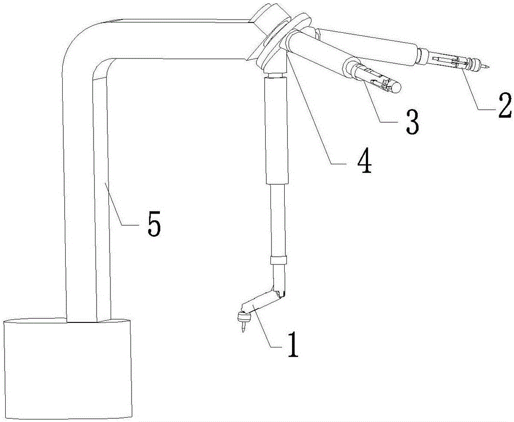
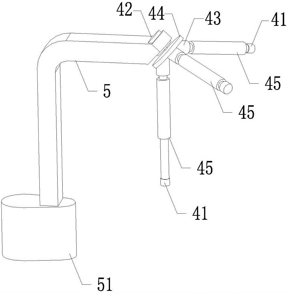
[0035] Such as figure 1 , figure 2 As shown, an engraving machine for engraving the inner wall of a container in this embodiment includes a bottom engraving assembly 1 for engraving the inner bottom surface of the container, a side engraving assembly 2 for engraving the inner side of the container, and an engraving assembly 2 for engraving the inner upper surface of the container. The upper surface engraving assembly 3, the assembly switching device 4 for switching the engraving assembly and the bracket 5 for fixing the assembly switching device 4; the component switching device 4 is installed on the bracket 5; the bottom surface engraving The component 1, the side engraving component 2 and the upper surface engraving component 3 are respectively installed on the component switching device 4;

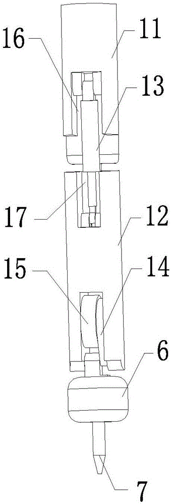
[0036] Such as image 3 , Figure 4 , Figure 11 , Figure 12 As shown, the bottom surface engraving assembly 1 includes a bottom surface engraving assembly female rod 11 for ins...

Embodiment 2

[0045] Such as figure 1 , figure 2 , an engraving machine for engraving the inner wall of a container in this embodiment includes a bottom engraving assembly 1 for engraving the inner bottom of the container, a side engraving assembly 2 for engraving the inner side of the container, and an upper engraving assembly for engraving the inner upper surface of the container. Surface engraving assembly 3, assembly switching device 4 for switching engraving assembly and bracket 5 for fixing assembly switching device 4; said assembly switching device 4 is installed on said support 5; said bottom surface engraving assembly 1 , the side engraving assembly 2 and the upper surface engraving assembly 3 are respectively installed on the assembly switching device 4;

[0046] Such as image 3 , Figure 4 , Figure 11 , Figure 12 , the bottom surface engraving assembly 1 includes a bottom surface engraving assembly female rod 11 for installing the bottom surface engraving assembly sub-r...


PUM


Abstract

The invention relates to the field of engraving machines, in particular to an engraving machine used for engraving the inner wall of a container. The engraving machine comprises a bottom face engraving assembly (1) used for engraving the bottom face of the interior of the container, a side face engraving assembly (2) used for engraving the side face of the interior of the container, an upper surface engraving assembly (3) used for engraving the upper surface of the interior of the container, an assembly switching device (4) used for switching the engraving assemblies and a supporting frame (5) used for fixing the assembly switching device (4). The assembly switching device (4) is arranged on the supporting frame (5); and the bottom face engraving assembly (1), the side face engraving assembly (2) and the upper surface engraving assembly (3) are arranged on the assembly switching device (4) separately. A user can engrave accurately and automatically on the inner wall of the container through the equipment, meanwhile, the work efficiency is high, and the application range is wide.

Description

technical field [0001] The invention relates to the field of engraving machines, in particular to an engraving machine for engraving the inner wall of a container. Background technique [0002] The art of carving the inner wall of cups and vases has very high ornamental and economic value, but in the existing technology, there is a lack of a kind of carving equipment for automatic carving of the inner wall of the container. Contents of the invention [0003] Aiming at the problems in the prior art, the invention provides an engraving machine for engraving the inner wall of a container, which can accurately and automatically engrave the inner wall of the container, and has high working efficiency and wide application range. [0004] The technical solution adopted by the present invention to solve the technical problem is: an engraving machine for engraving the inner wall of a container, including a bottom engraving assembly for engraving the inner bottom of the container, a...

Claims


Application Information

Patent Timeline
IPC IPC(8): B44B1/00B44B1/06
CPCB44B1/00B44B1/003B44B1/06B44B3/005B44B3/006B44B3/06B44B3/061B44B3/063B44B2700/04B44B2700/12
Inventor 林方杰
Owner 山东润蒙应急救援装备有限公司
Why Eureka
Try Eureka