Fine positioning automatic clamping and unloading device on the belt

An automatic clamping and unloading device technology, applied in the direction of conveyor control devices, transportation and packaging, conveyor objects, etc., can solve problems such as low work efficiency, inaccurate positioning, and difficulty in realizing automatic production, so as to improve work efficiency , high market competitiveness, guaranteed stability and accuracy

Active Publication Date: 2019-05-14
东莞东聚电子电讯制品有限公司
View PDF7 Cites 0 Cited by
  • Summary
  • Abstract
  • Description
  • Claims
  • Application Information

AI Technical Summary

Problems solved by technology

[0003] For various camera module function testing processes, the camera module is generally placed in the jig first, and then the jig is placed on the belt for transmission. When it is transferred to a certain test station, the jig is manually placed Picking and placing the jig in the test station, and then testing, its work efficiency is low, and the positioning is not accurate enough when placing the jig in the test station, it is difficult to realize automatic production
[0004] In order to improve work efficiency, the jig is picked up by the manipulator and placed in the test station, and then tested, but the positioning is still not accurate enough, resulting in low test accuracy of the test station, which cannot meet the production needs

Method used


Image

  • Fine positioning automatic clamping and unloading device on the belt
  • Fine positioning automatic clamping and unloading device on the belt
  • Fine positioning automatic clamping and unloading device on the belt

Examples


Embodiment Construction

[0019] The present invention will be further described below in conjunction with specific embodiments and accompanying drawings.

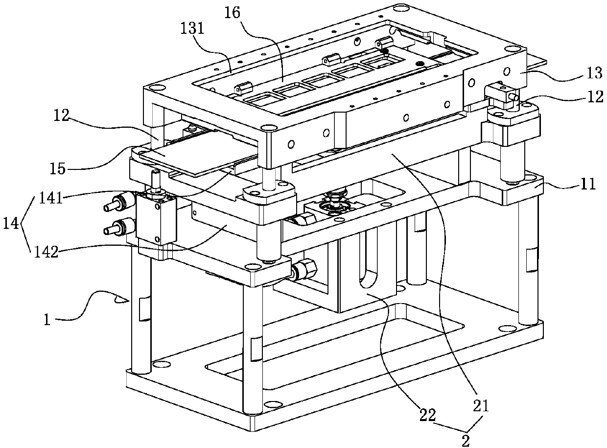
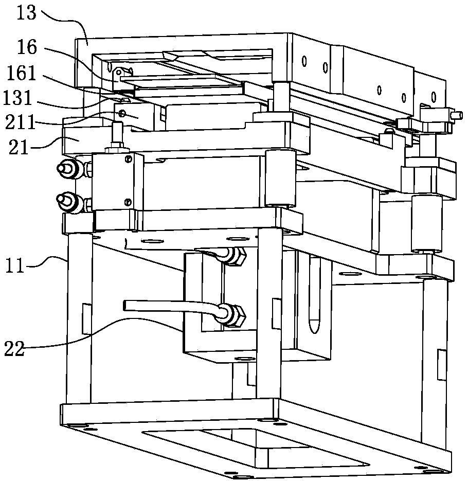
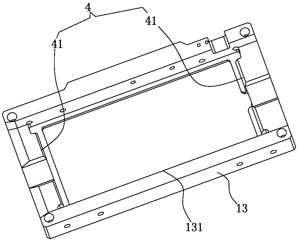
[0020] See Figure 1-5 As shown, it is a precise positioning automatic clamping and unloading device on the belt, which includes: a frame 1 and a lifting mechanism 2 installed on the frame 1 .

[0021] Described frame 1 comprises base frame 11, some guide rods 12 that are installed on the base frame 11 and the top board 13 that is fixed on guide rod 12 tops and the belt base assembly 14 that is fixed on base frame 11, and this belt base assembly 14 wears on A belt 15 is provided with a jig 16 on the belt 15, wherein a window 131 for exposing the belt 15 is provided on the top plate 13; The support plate 141 and the belt seat 142 fixed on the support plate 141 are provided with a belt groove 143 for the belt to pass through. The side of the top plate 13 is provided with a detection probe 17. When the detection probe 17 detects that the jig 16 is c...


PUM


Abstract

The invention discloses an accurate positioning and automatic clamping and discharging device on a belt. The accurate positioning and automatic clamping and discharging device comprises a machine frame and a lifting mechanism. The machine frame comprises an underbed, guide rods installed on the underbed, a top plate fixed to the top ends of the guide rods, and a belt seat assembly fixed to the underbed. The belt is arranged on the belt seat assembly in a penetrating mode. A jig is arranged on the belt. A window is formed in the top plate. The lifting mechanism comprises a lifting seat connected to the guide rods in a sleeving mode, and an air cylinder assembly which is installed on the machine frame and used for driving the lifting seat to ascend and descend relative to the top plate. The upper end of the lifting seat is provided with a plurality of protruding seats used for jacking up the jig, and a first positioning mechanism used for positioning the jig is arranged on the protruding seats. The lower end of the top plate is provided with a second positioning mechanism used for positioning the jig. According to the accurate positioning and automatic clamping and discharging device, the jig can be automatically clamped, dual positioning is achieved through the first positioning mechanism and the second positioning mechanism, the clamping stability and accuracy are guaranteed, and the effect that the jig is accurately positioned between the lifting seat and the top plate can be guaranteed; and after detection is completed, the purpose of automatic discharging can be achieved.

Description

Technical field: [0001] The invention relates to the field of processing technology, in particular to an automatic clamping and unloading device for precise positioning on a belt. Background technique: [0002] In the field of processing technology, the belt is a necessary component of the production line, used to convey the processed products or the products to be inspected. [0003] For various camera module function testing processes, the camera module is generally placed in the jig first, and then the jig is placed on the belt for transmission. When it is transferred to a certain test station, the jig is manually placed Picking and placing the jig in the test station for testing is inefficient, and the positioning of the jig in the test station is not precise enough, making it difficult to realize automatic production. [0004] In order to improve work efficiency, the jig is picked up by the manipulator and placed in the test station for testing. However, the positionin...

Claims


Application Information

Patent Timeline
Patent Type & Authority Patents(China)
IPC IPC(8): B65G43/08B65G47/22B65G47/34
CPCB65G43/08B65G47/22B65G47/34B65G2203/0233B65G2203/042
Inventor 潘永太肖荣辉杨富斗胡亚辉
Owner 东莞东聚电子电讯制品有限公司
Why Eureka
Try Eureka