
Novel stretching rotary manipulator

A rotating manipulator, a new type of technology, applied in the direction of manipulators, conveyor objects, chucks, etc., can solve the problems of low production efficiency, small gap between batteries and batteries, water stains, etc., to improve production efficiency and shorten loading and unloading time Effect

Inactive Publication Date: 2017-05-10
深圳市泽诚自动化设备有限公司
View PDF11 Cites 15 Cited by
  • Summary
  • Abstract
  • Description
  • Claims
  • Application Information

AI Technical Summary

Problems solved by technology

One type of existing cleaning machine is to put multiple batteries into the cleaning basket, and put the whole cleaning basket into the ultrasonic cleaning equipment for cleaning. Water droplets, this cleaning method has high efficiency, but because the gap between the batteries is not large, the water droplets on the surface of the battery cannot be blown off well when the wind is cut, and the water droplets on the battery surface will cause the battery to dry during drying Formation of water stains on the surface of the battery
Another structure is that the single row of batteries is put into the cleaning tank in an assembly line, and then the batteries are taken out from the cleaning tank in a single row to the assembly line, and then the water droplets on the battery surface are blown off by wind cutting. This method is more advanced than the previous one. This method can better blow off the water droplets on the surface of the battery to ensure the cleanliness of the battery surface after the battery is dried, but because the single-row battery is cleaned in the ultrasonic cleaning tank, the production efficiency is relatively low

Method used


Image

  • Novel stretching rotary manipulator
  • Novel stretching rotary manipulator

Examples


Embodiment Construction

[0021] In order to make the object, technical solution and advantages of the present invention clearer, the present invention will be further described in detail below in conjunction with the accompanying drawings and embodiments. It should be understood that the specific embodiments described here are only used to explain the present invention, not to limit the present invention.

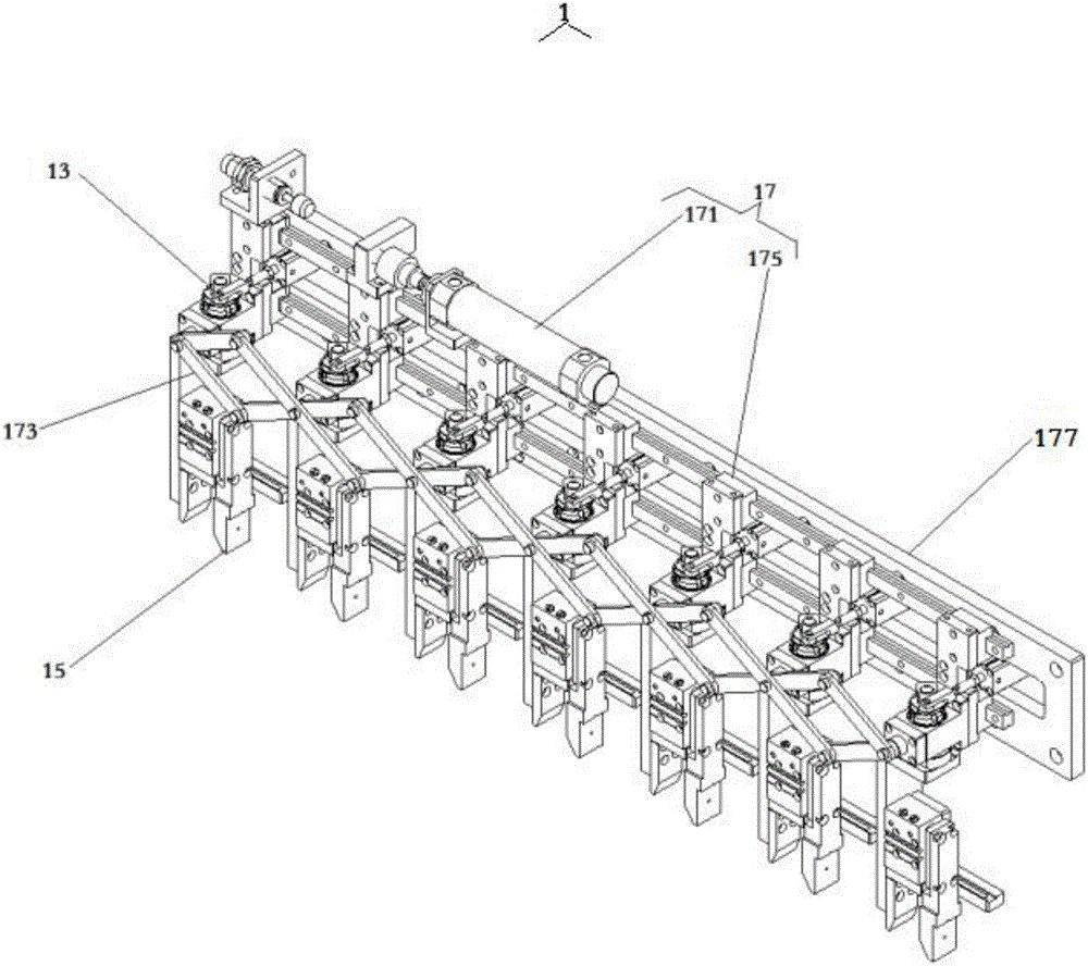
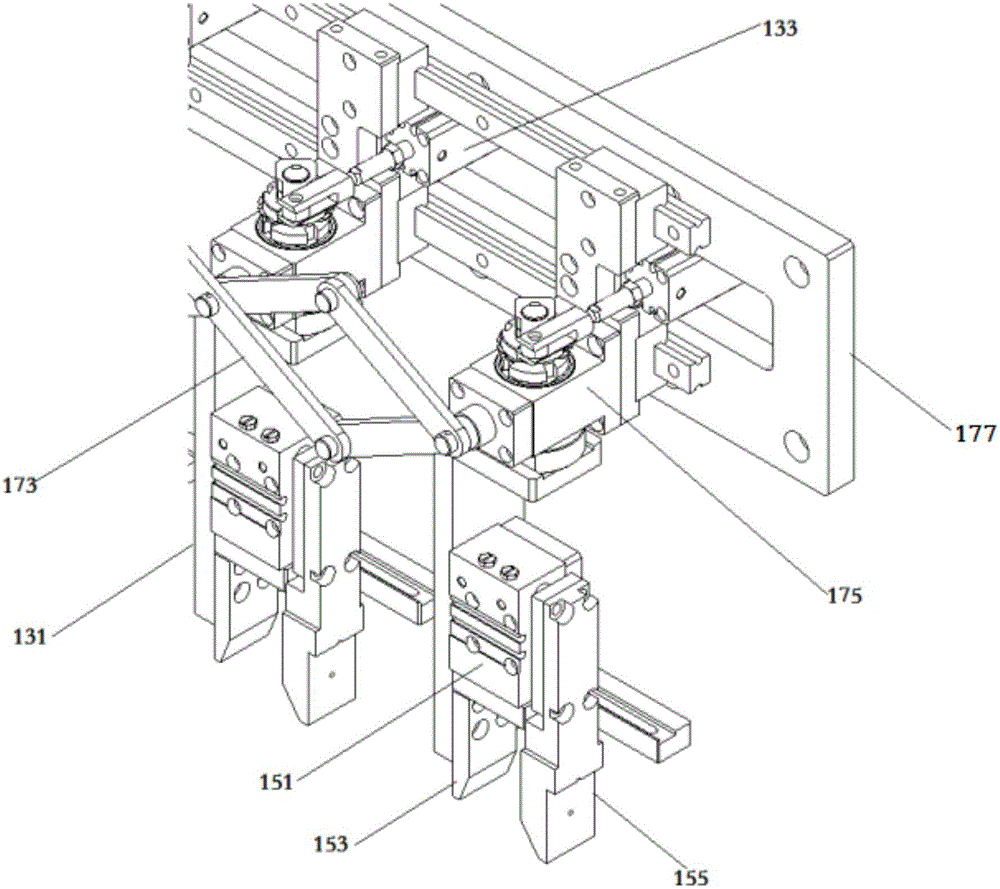
[0022] see figure 1 with figure 2 , a novel stretching rotary manipulator 1 of the present invention includes a stretching mechanism assembly 17, a rotating mechanism assembly 13, and a gripper mechanism assembly 15; The hinge driving cylinder 171, the cross-joint junction of each hinge 173 is connected with the linear guide rail 177 through the connecting block 175, when the hinge driving cylinder 171 drives the hinge 173 to expand and contract, the connecting block 175 moves along the guide rail on the linear guide rail 177; The rotating mechanism assembly 13 includes several rotating seats 13...


PUM


Abstract

The invention provides a novel stretching rotary manipulator. The novel stretching rotary manipulator comprises a stretching mechanism component, a rotary mechanism component and a clamping jaw mechanism component, wherein the stretching mechanism component comprises a linear guide rail, hinges and a hinge driving cylinder, and the junctions of cross joints of the hinges are connected with the linear guide rail through connection blocks; the rotary mechanism component comprises a plurality of rotary seats and rotary seat driving cylinders, and the rotary seats are fixed on the connection blocks through rotating shafts; and the clamping jaw mechanism component comprises a plurality of independent clamping jaw units. By adoption of the design, a plurality of batteries can be grabbed at a time, directional rotation of the plurality of batteries can be finished at a time, and the distance between every two batteries is increased, so that remarkable shortening of loading and unloading time for cleaning of the batteries is facilitated, and the production efficiency is improved. Water drops on the surfaces of the batteries can be blown off when the batteries are subject to upper-order wind shearing; the distances between the batteries are increased in the way that the cylinder drives the hinges, so that the intervals between the batteries can be the same; and the clamping jaw driving cylinders are adjustable in position to adapt to loading and unloading of the batteries with different widths.

Description

[0001] [technical field] [0002] The invention relates to the technical field of manipulator structures, in particular to a novel stretching rotary manipulator with high production efficiency, simple structure, low manufacturing cost, and can significantly shorten the loading and unloading time for cleaning batteries. [0003] [Background technique] [0004] The battery cleaning machine is a special equipment for cleaning the shell of the square battery. One type of existing cleaning machine is to put multiple batteries into the cleaning basket, and put the whole cleaning basket into the ultrasonic cleaning equipment for cleaning. Water droplets, this cleaning method has high efficiency, but because the gap between the batteries is not large, the water droplets on the surface of the battery cannot be blown off well when the wind is cut, and the water droplets on the battery surface will cause the battery to dry during drying Formation of water stains on the surface of the bat...

Claims


Application Information

Patent Timeline
IPC IPC(8): B65G47/90B25J15/00B25J18/04
CPCB65G47/902B25J15/0052B25J18/025B25J18/04
Inventor 李建强王阳
Owner 深圳市泽诚自动化设备有限公司
Learn More