Line-passing screw drilling tool

A screw drilling tool and line-passing technology, which is applied in the direction of drill pipe, drill pipe, drilling equipment, etc., can solve the problems of screw drilling tool line-passing, achieve the effects of shortening the length, simplifying the system structure, and reducing drilling risks

Inactive Publication Date: 2017-05-10
北京赛诺凤凰能源科技有限公司
View PDF15 Cites 19 Cited by
  • Summary
  • Abstract
  • Description
  • Claims
  • Application Information

AI Technical Summary

Problems solved by technology

[0004] At present, the market has not completely solved the problem of the screw drilling tool (also known as the mud motor) passing the line. The measuring instrument connected to the lower end of the screw cannot transmit the power supply or data signal through the screw drilling tool to the instrument connected to the upper end of the screw drilling tool through a wired connection.

Method used


Image

  • Line-passing screw drilling tool
  • Line-passing screw drilling tool
  • Line-passing screw drilling tool

Examples


Embodiment 1

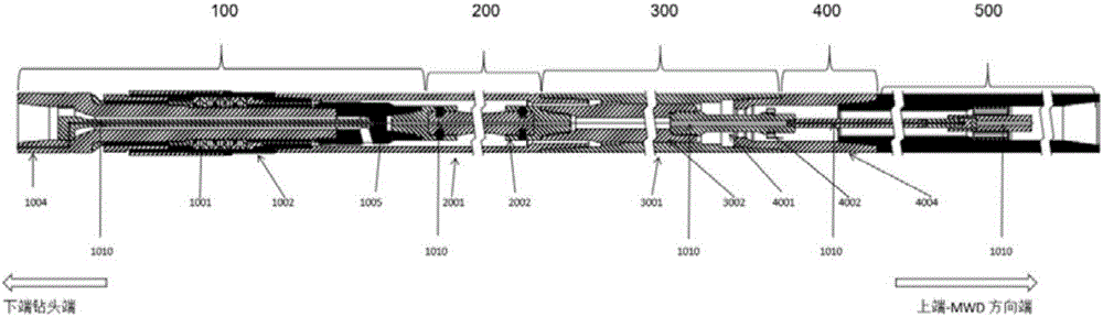
[0049] Such as figure 1 , figure 2 , an over-the-line screw drilling tool, including a transmission assembly 100, a cardan shaft assembly 200, a motor assembly 300, and an anti-drop assembly 400 arranged in sequence:

[0050] Anti-drop assembly 400 includes anti-drop housing 4004, anti-drop shaft 4001 and anti-drop nut 4002, anti-drop housing 4004 is connected with stator housing 3001 of motor assembly 300, and anti-drop nut 4002 is installed on anti-drop shaft 4001 On the top, the anti-drop shaft 4001 is installed inside the anti-drop housing 4004, and the anti-drop shaft 4001 is connected to the rotor 3002 of the motor assembly 300; the anti-drop shaft 4001 is provided with an anti-drop shaft inner hole;

[0051] The motor assembly 300 includes a stator housing 3001 and a rotor 3002. The rotor 3002 is installed in the stator housing 3001. The stator housing 3001 is connected to the housing 2001 of the cardan shaft assembly 200. The rotor 3002 is connected to the cardan sha...

Embodiment 2

[0057] Such as Figure 5 , in this embodiment, on the basis of Embodiment 1, a conversion compensation assembly 500 is also provided, including a wire passing shaft 5001-01, a conductive rotor 5002-01, a conductive stator 5003-01, a centralizer 5004-01, compensation and conductive The device 5005-01 and the conversion compensation housing 5006-01, the compensation and conductive device 5005-01 are installed in the conversion compensation housing 5006-01 through the centralizer 5004-01, the conductive rotor 5002-01 communicates with the conductive stator 5003-01, And installed together in the compensation and conductive device 5005-01, the two ends of the wire shaft 5001-01 are respectively axially connected with the anti-drop shaft 4001 and the conductive rotor 5002-01, and a wire hole is drilled in the middle of the wire shaft 5001-01, and the power supply and After the signal line passes through the line hole, the inside of the compensation and conductive device 5005-01, it ...

Embodiment 3

[0059] Such as Figure 6 , in this embodiment, on the basis of Embodiment 1, a conversion compensation assembly 500 is also provided, including a wire passing shaft 5001-01, a conductive rotor 5002-01, a conductive stator 5003-01, a centralizer 5004-01, compensation and conductive The device 5005-01 and the conversion compensation housing 5006-01, the compensation and conductive device 5005-01 are installed in the conversion compensation housing 5006-01 through the centralizer 5004-01, the conductive rotor 5002-01 communicates with the conductive stator 5003-01, And installed together in the compensation and conductive device 5005-01, the two ends of the wire shaft 5001-01 are respectively axially connected with the anti-drop shaft 4001 and the conductive rotor 5002-01, and a wire hole is drilled in the middle of the wire shaft 5001-01, and the power supply and After the signal line passes through the line hole, compensation and conductive device 5005-01, it is directly connec...


PUM


Abstract

The invention relates to a line-passing screw drilling tool comprising a driving assembly, a universal shaft assembly, a motor assembly and a falling-proof assembly which are arranged in sequence. The line-passing screw drilling tool has the advantages that (1), a complete line-passing connection of a screw from the upper end to the lower end is achieved; (2), the lower end of the screw can be connected with an independent measuring short section or module / well logging short section or module such as a near-bit geosteering measuring short section or rotating guiding system; (3), the power supply and signal bidirectional communication of instruments of the upper end and the lower end of the screw are achieved; (4), the centralized and uniform power supply through the upper end of the screw can be selected, so that the system structure is simplified; and (5), the measuring short section between a drill and the screw is shortened, and the well drilling risk is reduced.

Description

technical field [0001] The patent of the present invention relates to the over-the-line connection solution technology of downhole screw drilling tools (also known as mud motors), and specifically relates to an over-the-line screw drilling tool. Realize the complete over-the-line connection from the upper end and the lower end of the screw drilling tool, so as to realize the power supply, data signal and instructions across the upper and lower ends of the screw drilling tool. The lower end of the screw rod can be connected to an independent measurement / logging sub or module, such as Near-bit geosteering measurement sub-section or rotary steerable system, etc., the data collected by the sub-section or module connected to the lower end of the screw drilling tool can be transmitted to the MWD (Measurement While Drilling Instrument) at the upper end of the screw through the threaded screw, and finally the corresponding drilling engineering parameters And geological survey paramete...

Claims


Application Information

Patent Timeline
Patent Type & Authority Applications(China)
IPC IPC(8): E21B17/00E21B47/12E21B7/04
CPCE21B7/04E21B17/003E21B47/12
Inventor 文趣群王玉东陈福正
Owner 北京赛诺凤凰能源科技有限公司
Why Eureka
Try Eureka