A layered ignition gas injection string

A gas injection pipe and gas injection technology, which is applied in wellbore/well components, production fluid, sealing/packing, etc., can solve the problem that fire-flooding wells cannot achieve multi-layer ignition and gas injection separately, and improve the fire-flooding effect. , Improve work efficiency and reduce construction costs

Active Publication Date: 2018-12-25
PETROCHINA CO LTD
View PDF5 Cites 0 Cited by
  • Summary
  • Abstract
  • Description
  • Claims
  • Application Information

AI Technical Summary

Problems solved by technology

[0003] In order to solve the problem that the existing fire flooding wells cannot achieve separate ignition and gas injection in multiple layers, the present invention provides a layered ignition gas injection string, which can realize multi-layer ignition and gas injection, and satisfies the Oil well ignition requirements, improving the operating efficiency of ignition wells

Method used


Image

  • A layered ignition gas injection string
  • A layered ignition gas injection string
  • A layered ignition gas injection string

Examples


Embodiment 1

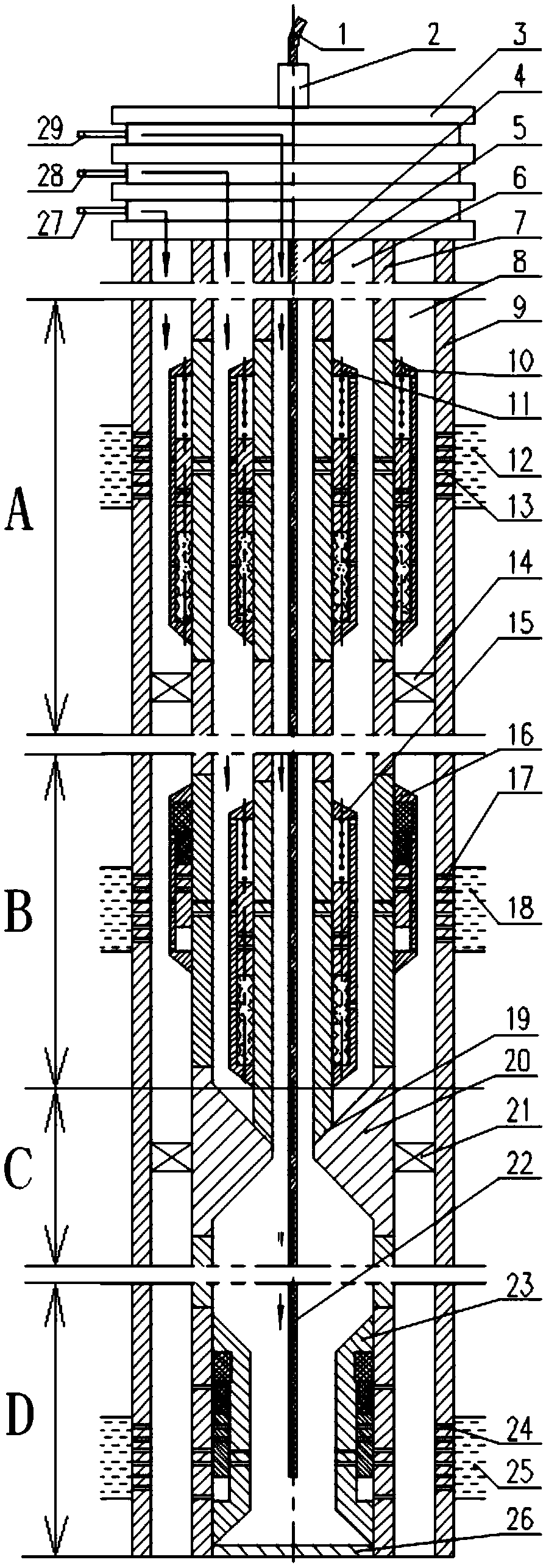
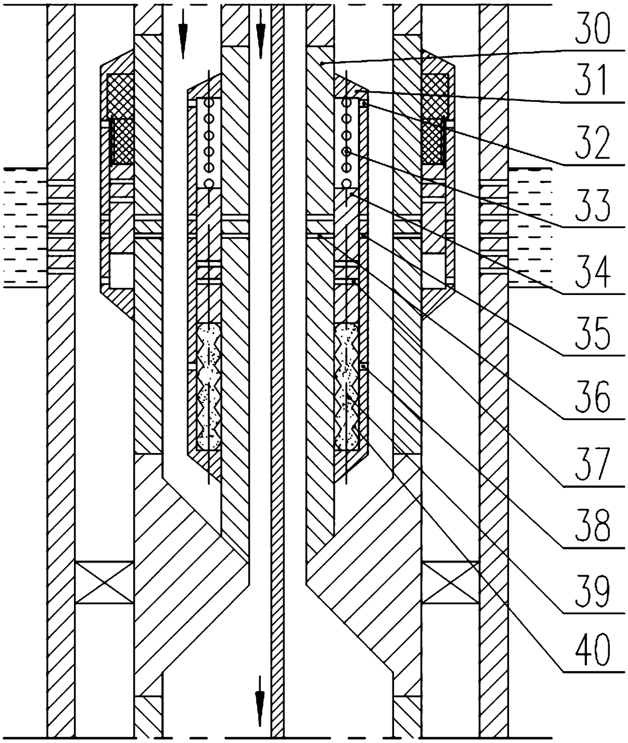
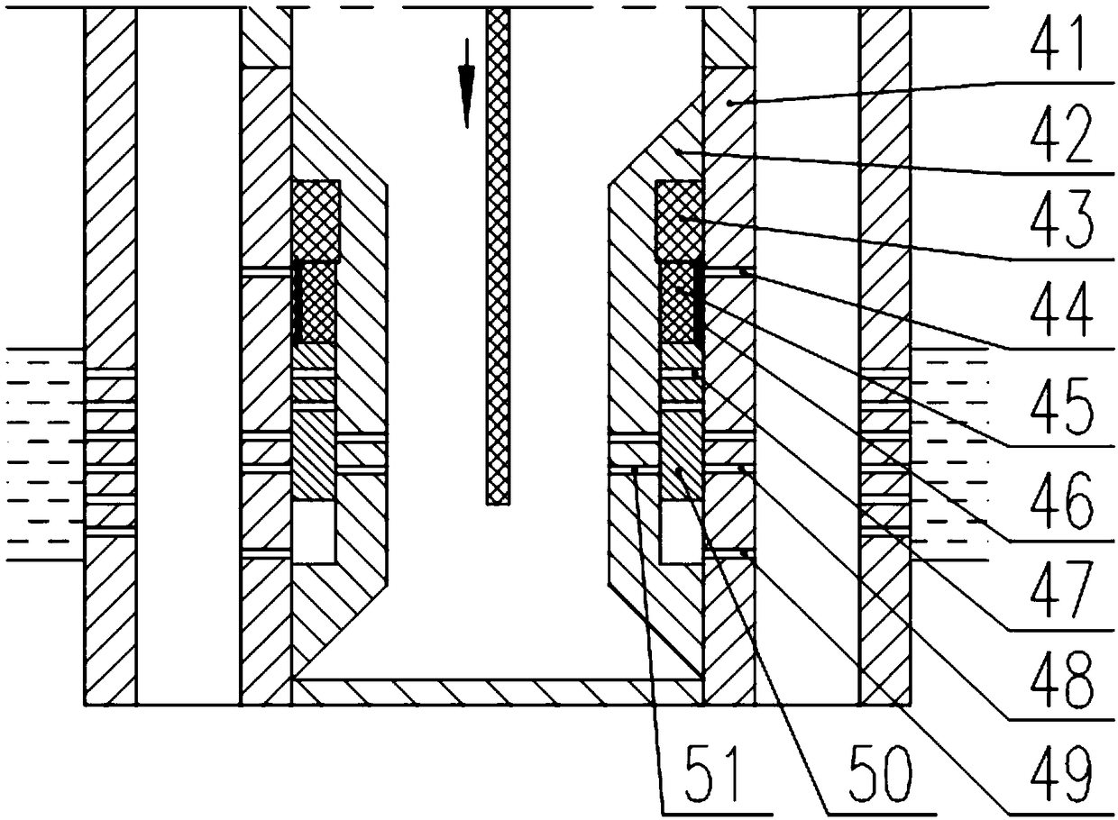
[0019] A layered ignition gas injection pipe string, including an inner pipe string 5 and an outer pipe string 7, both of which are in an upright state, the outer pipe string 7 is sleeved outside the inner pipe string 5, and the outer pipe string An annular space is formed between 7 and the inner pipe string 5, and the outer pipe string 7 contains the first gas injection valve 10, the fourth gas injection valve 16 and the fifth gas injection valve 23 arranged sequentially from top to bottom, and the inner pipe string 5 It contains the second gas injection valve 11 and the third gas injection valve 15 arranged in sequence from top to bottom, the position of the first gas injection valve 10 corresponds to the position of the second gas injection valve 11, and the position of the third gas injection valve 15 The position corresponds to the position of the fourth gas injection valve 16; the first gas injection valve 10, the second gas injection valve 11 and the third gas injection ...

Embodiment 2

[0033] The layered ignition gas injection string introduced in Example 1 is mainly for ignition and gas injection of three oil layers. This embodiment introduces a layered ignition gas injection string suitable for ignition and gas injection of two oil layers.

[0034] A layered ignition gas injection pipe string, comprising an inner pipe string 5 and an outer pipe string 7, the outer pipe string 7 is sleeved outside the inner pipe string 5, an annular space is formed between the outer pipe string 7 and the inner pipe string 5, and the outer pipe string 7 The column 7 contains the first gas injection valve 10 and the fourth gas injection valve 16 arranged in sequence from top to bottom, and the inner pipe column 5 contains the second gas injection valve 11 and the third gas injection valve arranged in sequence from top to bottom 15. The position of the first gas injection valve 10 corresponds to the position of the second gas injection valve 11, and the position of the third ga...

Embodiment 3

[0038] The layered ignition gas injection string introduced in Example 1 is mainly for ignition and gas injection of three oil layers. This embodiment introduces a layered ignition gas injection string suitable for ignition and gas injection of two oil layers.

[0039] A layered ignition gas injection pipe string, comprising an inner pipe string 5 and an outer pipe string 7, the outer pipe string 7 is sleeved outside the inner pipe string 5, an annular space is formed between the outer pipe string 7 and the inner pipe string 5, and the outer pipe string 7 The column 7 contains the fourth gas injection valve 16 and the fifth gas injection valve 23 arranged sequentially from top to bottom, and the inner pipe column 5 contains the third gas injection valve 15, the position of the third gas injection valve 15 and the fourth gas injection valve. The position of the gas valve 16 is corresponding; the third gas injection valve 15 is a temperature-controlled gas injection valve that ca...


PUM


Abstract

The invention provides a layered ignition and gas injection pipe column which comprises an inner pipe column (5) and an outer pipe column (7), wherein the outer pipe column (7) comprises a first gas injection valve (10), a fourth gas injection valve (16) and a fifth gas injection valve (23) which are sequentially arranged from top to bottom, the inner pipe column (5) comprises a second gas injection valve (11) and a third gas injection valve (15) which are sequentially arranged from top to bottom, the first gas injection valve (10), the second gas injection valve (11) and the third gas injection valve (15) are all temperature control gas injection valves capable of being switched by multiple times, and the fourth gas injection valve (16) and the fifth gas injection valve (23) are both temperature control gas injection valves capable of being switched by only one time, so that the temperature control gas injection valves capable of being switched by only one time can be opened when the temperature in the valves is greater than or equal to a preset value. According to the layered ignition and gas injection pipe column provided by the invention, multi-layer ignition and gas injection can be realized, the requirement of ignition of an oil well is meet, and the operation efficiency of igniting the well is improved.

Description

technical field [0001] The invention relates to the field of oil exploitation equipment, in particular to a layered ignition gas injection string. Background technique [0002] The fire flooding process is an important conversion method in the late stage of oilfield heavy oil development. Due to the limitation of the column structure and technology, during the ignition process of the mobile igniter (such as Chinese patent CN103147733B, published on June 12, 2013, the "Fire Burning Oil Layer Retractable Electric Ignition and Monitoring System"), It can only perform single-layer ignition, but cannot realize separate ignition and gas injection of multiple layers, and cannot meet the needs of special oil wells. Contents of the invention [0003] In order to solve the problem that the existing fire flooding wells cannot achieve separate ignition and gas injection in multiple layers, the present invention provides a layered ignition gas injection string, which can realize multi...

Claims


Application Information

Patent Timeline
Patent Type & Authority Patents(China)
IPC IPC(8): E21B43/243E21B43/24E21B34/06
CPCE21B34/06E21B43/24E21B43/243
Inventor 杨显志李树全宋志军张福兴李广富王健骁于晓聪穆磊袁天瑜许丹袁东旭崔洪志赵云峰赵超刘京松李庆烈孙景
Owner PETROCHINA CO LTD
Why Eureka
Try Eureka