
A wall grinding path planning method, device, electronic equipment and storage medium

A path planning and shortest path algorithm technology, applied in grinding/polishing equipment, grinding automatic control devices, metal processing equipment, etc., can solve the problems of easy damage to the grinding head, poor grinding effect, and low efficiency of grinding operations, and achieve Save construction costs, reduce losses, and solve the effect of low efficiency in grinding operations

Active Publication Date: 2021-03-02
GUANGDONG BOZHILIN ROBOT CO LTD
View PDF9 Cites 0 Cited by
  • Summary
  • Abstract
  • Description
  • Claims
  • Application Information

AI Technical Summary

Problems solved by technology

[0004] The purpose of the embodiments of the present application is to provide a wall grinding path planning method, device, electronic equipment, and storage medium. By optimizing the grinding path, the protruding area can be effectively polished, and the existing method can solve the problem of low grinding efficiency and poor grinding effect. Poor and easy to damage the grinding head

Method used


Image

  • A wall grinding path planning method, device, electronic equipment and storage medium
  • A wall grinding path planning method, device, electronic equipment and storage medium
  • A wall grinding path planning method, device, electronic equipment and storage medium

Examples


Embodiment 2

[0129] The embodiment of the present application provides a wall grinding path planning device, such as Figure 14 Shown is the structural block diagram of the path planning device. The unit includes:

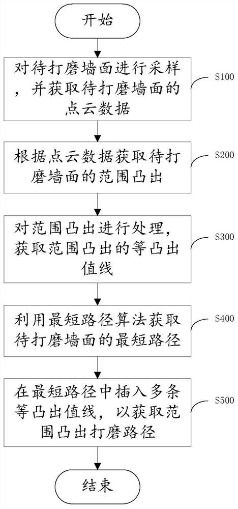
[0130] The point cloud data acquisition module 100 is used to sample the wall surface to be polished, and obtain the point cloud data of the wall surface to be polished;

[0131] A range protrusion acquisition module 200, configured to acquire the range protrusion of the wall surface to be polished according to the point cloud data;

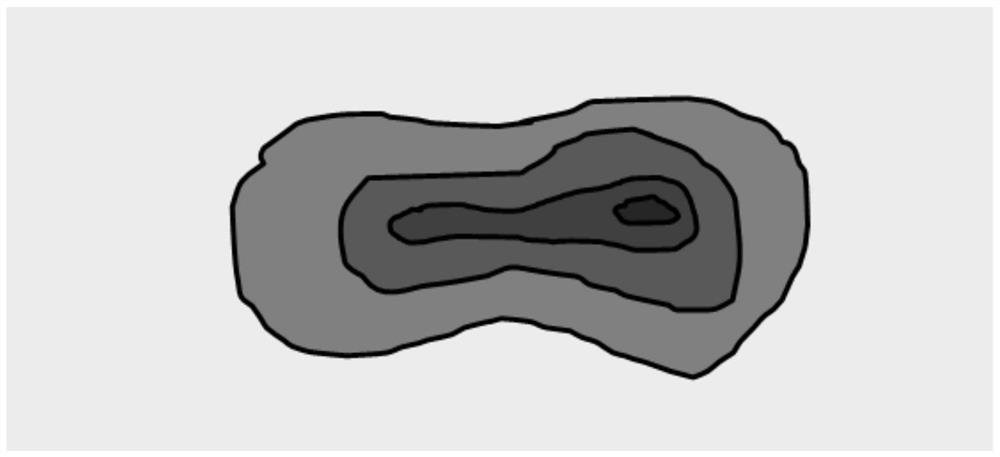
[0132] The contour contour acquisition module 300 is configured to process the range protrusion, so as to obtain multiple contour contours of the range protrusion;

[0133] The shortest path obtaining module 400 is used for the shortest path algorithm to obtain the shortest path of the wall surface to be polished;

[0134] The grinding path acquisition module 500 is configured to insert a plurality of isobulging value lines in the shortest path...

Embodiment 3

[0153] An embodiment of the present application provides an electronic device for wall grinding path planning, the electronic device includes a memory and a processor, the memory is used to store a computer program, and the processor runs the computer program to enable the computer device to execute the above-mentioned embodiment 1. The wall grinding path planning method described above.

[0154] The embodiment of the present application also provides a readable storage medium, where computer program instructions are stored in the readable storage medium, and when the computer program instructions are read and executed by a processor, the method described in Embodiment 1 is executed. Path planning method for wall grinding.


PUM


Abstract

Embodiments of the present application provide a route planning method, device, electronic equipment, and storage medium, which relate to the technical field of operating equipment route planning. The method includes: sampling the wall surface to be polished, and obtaining point cloud data of the wall surface to be polished; obtaining the range projection of the wall surface to be polished according to the point cloud data; Processing, obtaining the isobulging value lines protruding in the range; using the shortest path algorithm to obtain the shortest path of the wall surface to be polished; inserting the plurality of isobulging value lines in the shortest path to obtain the range Convex sanding paths. The method effectively grinds the protruding area by optimizing the grinding path, and solves the problems of low grinding efficiency, poor grinding effect and easy damage to the grinding head in the existing method.

Description

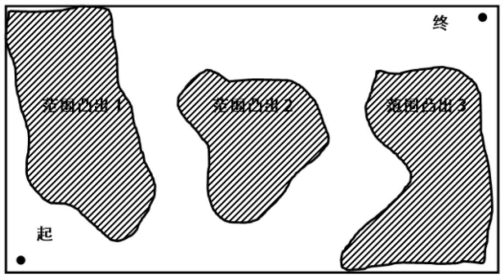
technical field [0001] The present application relates to the technical field of path planning for operating equipment, and in particular, relates to a wall grinding path planning method, device, electronic equipment, and storage medium. Background technique [0002] At this stage, the main structure of the building is constructed by pouring. Since the concrete base wall needs to meet the acceptance criteria of -5 and +10mm, the wall without the base of the concrete wall is prone to hollowing after plastering and other processes , cracking and other phenomena, based on these reasons, it is necessary to grind the base of the concrete wall after the removal of the formwork. [0003] Existing wall grinding methods, such as bottom-up or top-down operations, do not effectively polish the protruding areas, resulting in low efficiency of grinding operations, poor grinding effects, and easy damage to the grinding head. Contents of the invention [0004] The purpose of the embodim...

Claims


Application Information

Patent Timeline
Patent Type & Authority Patents(China)
IPC IPC(8): B24B7/18B24B51/00
CPCB24B7/182B24B51/00
Inventor 袁皓男陈航英陶志成冯永林何素韵高正玉李有肖泽钰吴自佑曹国舒远
Owner GUANGDONG BOZHILIN ROBOT CO LTD
Learn More