Load controllable engine braking device and engine braking method

A technology of engine braking and engine, applied in the direction of engine control, engine components, machine/engine, etc., can solve the problems of large braking load, etc., and achieve the goals of reducing braking load, compact structure, improving reliability and durability Effect

Active Publication Date: 2019-09-27
SHANGHAI UNIVERSOON AUTOPARTS CO LTD
View PDF7 Cites 0 Cited by
  • Summary
  • Abstract
  • Description
  • Claims
  • Application Information

AI Technical Summary

Problems solved by technology

In general, compression-release engine braking has greater braking power than vented braking, but it also produces greater braking loads, and is especially unsuitable for flat-bottomed tappet engines

Method used


Image

  • Load controllable engine braking device and engine braking method
  • Load controllable engine braking device and engine braking method
  • Load controllable engine braking device and engine braking method

Examples


Embodiment 1

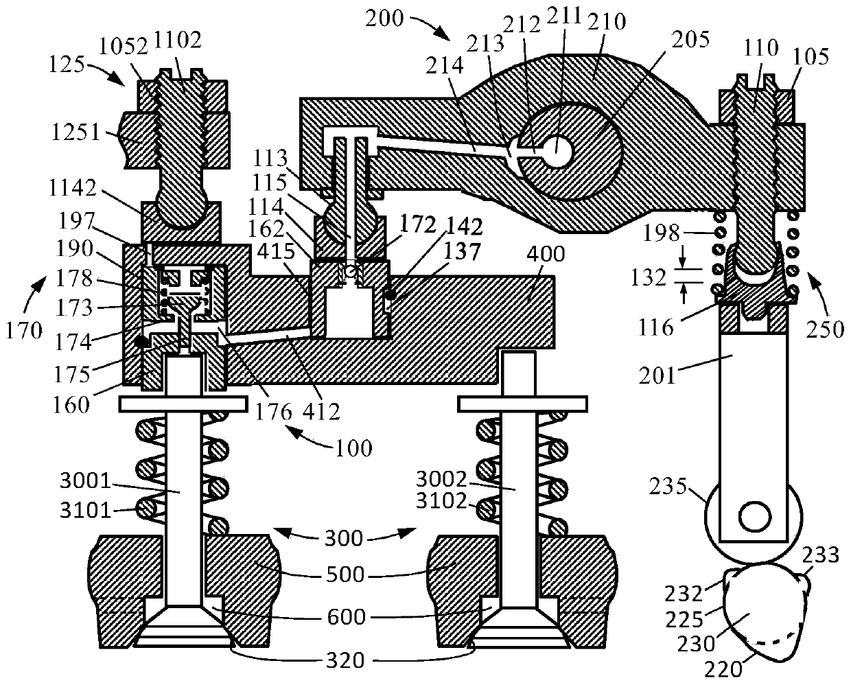
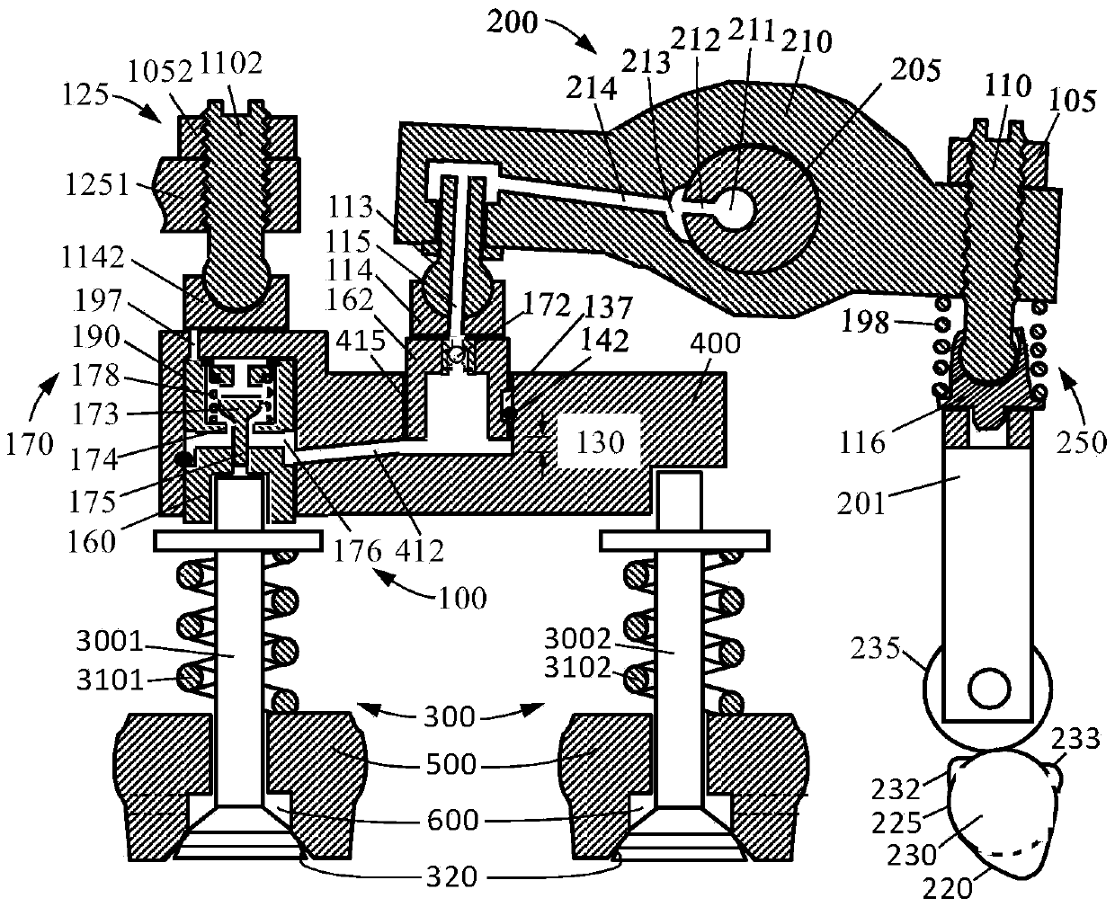
[0020] Such as figure 1 with figure 2 As shown, Embodiment 1 of the load-controllable engine braking device of the present invention is in the positions of "OFF" (the oil supply mechanism cuts off oil) and "ON" (the oil supply mechanism supplies oil). figure 1 with figure 2 It includes three main components: a valve actuator 200 of the engine, a valve 300 (including a first valve 3001 and a second valve 3002 ) and a load-controllable engine brake drive mechanism 100 .

[0021] The valve actuator 200 includes a cam 230 , a cam follower 235 , a push rod 201 , a rocker arm 210 and a valve bridge 400 . Together, the valve actuator 200 and the valve 300 may be referred to as a valve drive chain. Usually, one end of the rocker arm 210 (close to the valve bridge 400 or close to the cam 230 ) is provided with a valve clearance adjusting mechanism. The valve gap adjusting mechanism in this embodiment includes a valve gap adjusting screw 110 arranged in a rocker arm 210 on one sid...

Embodiment 2

[0037] Such as Figure 5 with Image 6 As shown, Embodiment 2 of the load-controllable engine braking device of the present invention is in the positions of "off" (the oil supply mechanism cuts off oil) and "on" (the oil supply mechanism supplies oil) respectively. The difference between this embodiment and the first embodiment above is that the box body in this embodiment adopts the rocker arm 210 of the engine. That is to say, the engine brake drive mechanism 100 is mainly integrated in the rocker arm 210 . The main piston hole 415 is arranged at one end of the rocker arm 210 and opens downward, and the auxiliary piston hole 190 is arranged at the other end of the rocker arm 210 and also opens downward. The outer end (lower side) of the main piston 162 in the main piston hole 415 is connected with the cam, and the outer end (lower side) of the auxiliary piston 160 in the auxiliary piston hole 190 is connected with the valve 3001 of the engine. An oil hole 197 is arranged ...


PUM


Abstract

The invention relates to a load-controllable engine braking method which comprises a process for preventing fluid pressure on an auxiliary piston in an engine braking device to a main piston. The engine braking device comprises a pressure-limiting mechanism, a pressure-limiting valve of the pressure-limiting mechanism is arranged between a main piston hole and an auxiliary piston hole, and the pressure-limiting valve is kept to be in the normal-open state through a pressure-limiting spring; a cam drives the main piston, the main piston drives the auxiliary piston through hydraulic pressure, an air valve of an engine is opened through the auxiliary piston and applies counter-acting force to the auxiliary piston, the pressure of fluid in the auxiliary piston hole is increased, pretightening force of a pressure-limiting spring on the pressure-limiting valve is overcome, the pressure-limiting valve is closed, and pressure of fluid on the auxiliary piston is prevented from being transmitted to the main piston. The pressure of the fluid on the auxiliary piston is transmitted to a stopping mechanism fixed to the engine rather than the cam of the engine. A box of the engine braking device comprises a valve bridge and a rocker of the engine. By means of the load-controllable engine braking method, loads on an engine air valve driving chain can be controlled, and the reliability and durability of the engine are increased.

Description

Technical field: [0001] The invention relates to the mechanical field, in particular to engine braking technology, in particular to a load-controllable engine braking device and an engine braking method. Background technique: [0002] Engine braking can be classified into compression release type braking and vent type braking. [0003] The compression release type braking of the engine is to open the exhaust valve in the second half of the engine piston compression stroke. A precedent for a compression-release brake was disclosed by Cummins in 1965 in US Patent No. 3,220,392, a braking system that transmits mechanical input through a hydraulic circuit to an exhaust valve to open. The hydraulic circuit typically includes a main piston that reciprocates within a main piston bore from a mechanical input to the engine, such as movement of an engine injection cam or movement of an adjacent exhaust cam. The movement of the main piston is transmitted to the auxiliary piston on th...

Claims


Application Information

Patent Timeline
Patent Type & Authority Patents(China)
IPC IPC(8): F01L13/06F01L1/26F02D13/04
Inventor 杨洲
Owner SHANGHAI UNIVERSOON AUTOPARTS CO LTD
Why Eureka
Try Eureka