Proportional control brake

Active Publication Date: 2019-07-25
HAMILTON SUNDSTRAND CORP
View PDF5 Cites 0 Cited by
  • Summary
  • Abstract
  • Description
  • Claims
  • Application Information

AI Technical Summary

Benefits of technology

The patent describes a proportional braking system for movable surfaces, such as those on an aircraft, that uses variable displacement brakes to apply a braking load to the surfaces in proportion to an input command. The system includes a brake driver that receives data reflective of the movement of the surfaces and issues the input command to the brakes based on the data. The brakes are designed to displace toward or away from braking engagement with the surfaces in response to the input command. The system can provide a more precise and efficient means of applying braking loads to movable surfaces and can be used in various types of vehicles, such as aircraft.

Problems solved by technology

For movable high-lift devices, movement control utilizes a dual, on-or-off operational state referred to as “bang-engaged” or “bang-disengaged.” However, this type of movement control can lead to other issues.
These include the fact that modern high-lift actuation systems require fast detections of failures but it is often the case that, upon detection of failure conditions such as asymmetries, skews or un-commanded motion, system response times to bring surface motion to a complete stop can be too long.
This delayed response time can result in excess damage to the system components and the airframe.

Method used


Image

  • Proportional control brake
  • Proportional control brake
  • Proportional control brake

Examples


Embodiment Construction

[0039]As will be described below, a proportional brake is provided for use on torque tubes (i.e., drive line systems) and / or on hydraulic or electric motors. The proportional brake includes a proportionally current controlled friction brake that allows for a variable applied brake force. This variable (proportional) controlled force to the break allows for precise braking for slat and flap system accelerations and decelerations including emergency stop conditions. The proportional brake could also be provided as a variable load drag during normal system operation. That is, while a brake is typically designed to be in the normally engaged state with no current applied, a proportional brake that is provided for use as an active drag brake can be designed for assumption of a normally disengaged state with no current applied.

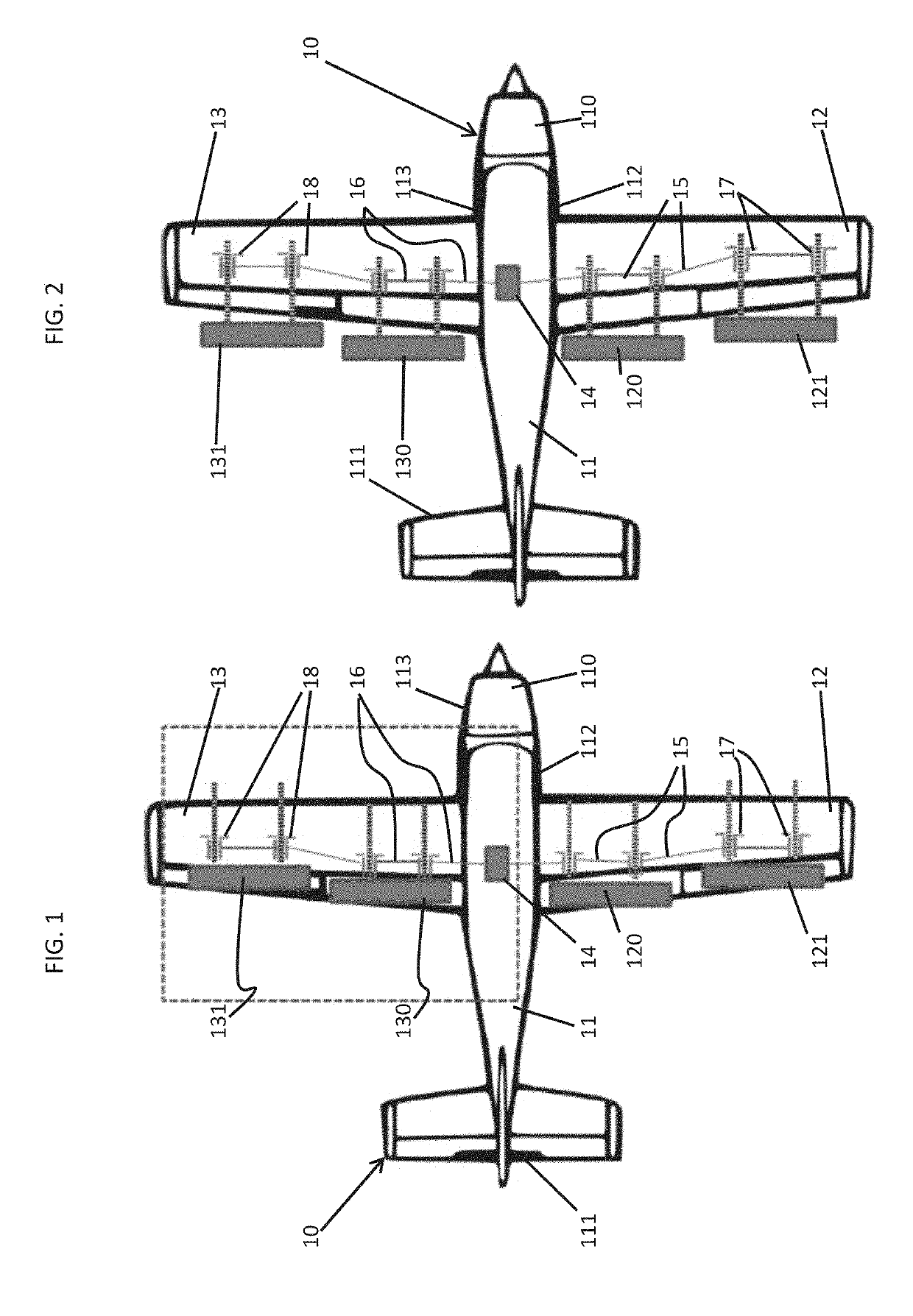
[0040]With reference to FIGS. 1 and 2, an aircraft 10 is provided. As shown in FIGS. 1 and 2, the aircraft 10 includes a fuselage 11 having a forward section 110, a...


PUM


Abstract

A proportional braking system is provided for use with a movable surface which is movable relative to a housing. The proportional braking system includes a variable displacement brake which is configured for displacement toward or away from braking engagement with the movable surface in proportion to an input command and a brake driver which is receptive of data reflective of movements of the movable surface relative to the housing and which issues the input command to the variable displacement brake in accordance with the data.

Description

BACKGROUND[0001]The following description relates to a proportional control brake and, more specifically, to a high-lift actuation system with a proportional control brake.[0002]In aircraft design and aerospace engineering, a high-lift device is a component or mechanism on an aircraft's wing that increases the amount of lift produced by the wing. The device may be a fixed component or a movable mechanism which is deployed when required. Common movable high-lift devices include wing flaps and slats. Fixed devices include leading edge root extensions and boundary layer control systems.[0003]For movable high-lift devices, movement control utilizes a dual, on-or-off operational state referred to as “bang-engaged” or “bang-disengaged.” However, this type of movement control can lead to other issues. These include the fact that modern high-lift actuation systems require fast detections of failures but it is often the case that, upon detection of failure conditions such as asymmetries, ske...

Claims


Application Information

Patent Timeline
IPC IPC(8): F16D55/36F16D65/16B64C9/14
CPCF16D55/36F16D65/16B64C9/14F16D2121/14F16D2121/22B64C2009/005B64C3/00B64C9/00B64C13/00B64D2045/001Y02T50/40
Inventor ANKNEY, DARRELL E.WLAZNIK, NICHOLAS
Owner HAMILTON SUNDSTRAND CORP
Why Eureka
Try Eureka