Rotary compressor and refrigeration device having the same
A technology of rotating compressors and rotors, which is applied to components of pumping devices for elastic fluids, rotary piston type/swing piston type pump components, mechanical equipment, etc., to increase pump oil volume and pump lift, and prevent sudden Effect of oil discharge and prevention of rotor overheating
- Summary
- Abstract
- Description
- Claims
- Application Information
AI Technical Summary
Problems solved by technology
Method used
Image
Examples
Embodiment 1
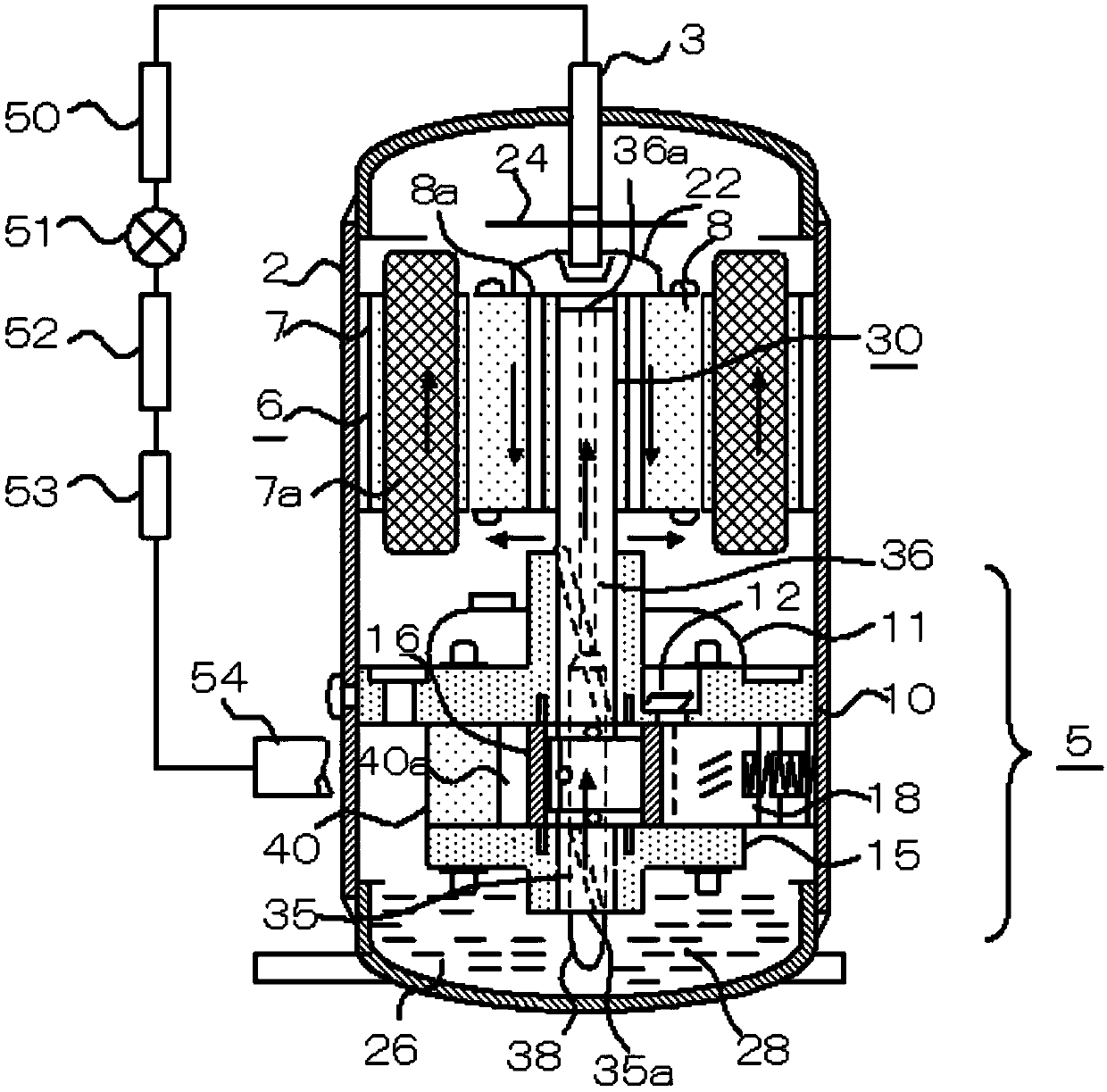
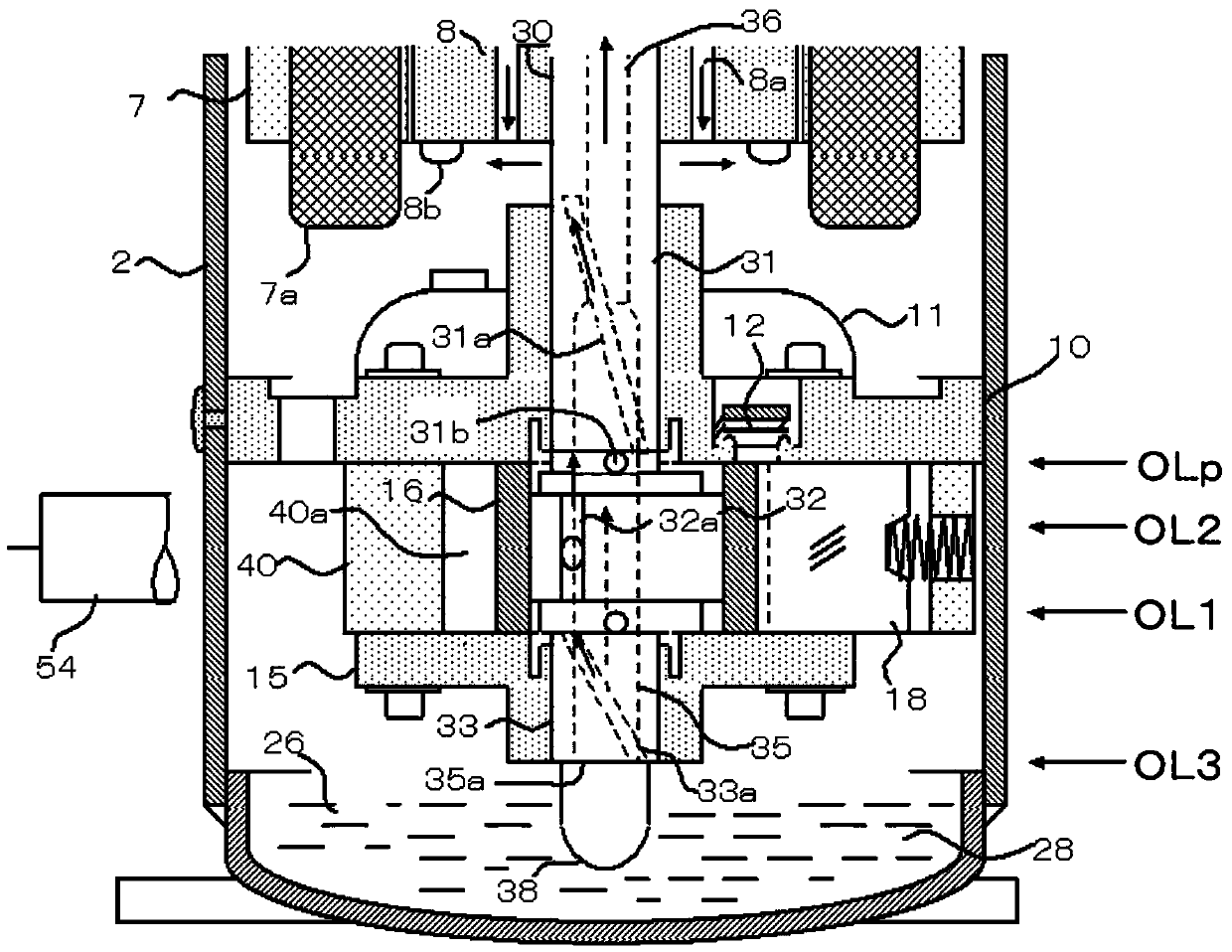
[0046] figure 1 and figure 2 Among them, an electric motor 6 (hereinafter referred to as motor 6 ) and a compression mechanism part 5 driven by the motor 6 are fixed on the inner peripheral wall of the sealed casing 2 (hereinafter referred to as casing 2 ) of the rotary compressor.
[0047] Lubricating oil 26 (hereinafter referred to as oil 26 or oil) is stored in an oil storage tank 28 disposed at the bottom of the housing 2 .
[0048] The compression mechanism part 5 includes: a main bearing 10 fixed to the inner peripheral wall of the housing 2, a cylinder 40, an auxiliary bearing 15, a crankshaft 30 slidingly engaged with the above two bearings, a piston 16 driven by the crankshaft 30 to rotate eccentrically, and a reciprocating cylinder. slide 18. An exhaust muffler 11 housing a valve device 12 is disposed on the main bearing 10 .
[0049] The crankshaft 30 is fixed by the rotor 8, and the crankshaft 30 includes: a main shaft 31 slidingly fitted with the main bearing ...
Embodiment 2
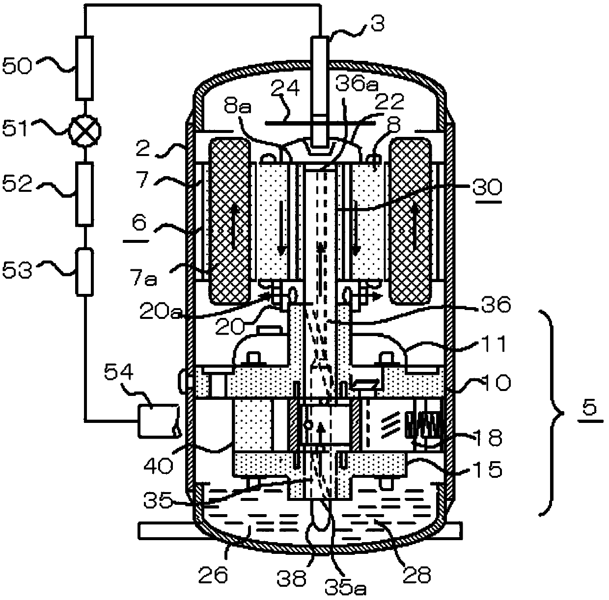
[0069] image 3 and Figure 4 In the shown embodiment 2, compared with the embodiment 1, in order to increase the pressure drop of the pump chamber, a rotating chamber 20 is added at the outlet of the rotor air hole 8a. On the outer peripheral wall of the rotary chamber 20, a plurality of cylindrical rotary windows 20a are arranged.
[0070] The rotation chamber 20 fixed to the lower end of the rotor 8 by the rotor rivet 8 b is located on the outer periphery of the main bearing 10 near the bearing upper end. This rotation gap (C) is designed to be 0.2mm or less in order to prevent gas leakage. In Embodiment 2, the rotation diameter of the rotation window 20 is larger than the rotation diameter of the rotor air hole 8a. By processing the diameter and shape of the rotation window 20, the pressure drop of the pump chamber 35 can be increased compared with the embodiment 1.
[0071] Under the condition that the oil level of the oil storage tank 28 is stable from the lower end (...
PUM
 Abstract
Description
Claims
Application Information
 - R&D
- Intellectual Property
- Life Sciences
- Materials
- Tech Scout
- Unparalleled Data Quality
- Higher Quality Content
- 60% Fewer Hallucinations
Browse by: Latest US Patents, China's latest patents, Technical Efficacy Thesaurus, Application Domain, Technology Topic, Popular Technical Reports.
© 2025 PatSnap. All rights reserved.Legal|Privacy policy|Modern Slavery Act Transparency Statement|Sitemap|About US| Contact US: help@patsnap.com


