High-precision crank shaft for speed reducer and machining method thereof

A processing method and crankshaft technology, applied in directions such as crankshafts, can solve the problems of numerous parts, high manufacturing costs, and high failure rates, and achieve the effects of reducing processing errors, reducing assembly errors, and reducing costs.

Inactive Publication Date: 2017-05-10
JOUDER PRECISION INDAL KUSN
View PDF5 Cites 4 Cited by
  • Summary
  • Abstract
  • Description
  • Claims
  • Application Information

AI Technical Summary

Problems solved by technology

[0002] The current crankshafts for reducers, especially the crankshafts used for robot RV reducers, require extremely high transmission precision. The crankshafts used for RV redu

Method used


Image

  • High-precision crank shaft for speed reducer and machining method thereof
  • High-precision crank shaft for speed reducer and machining method thereof
  • High-precision crank shaft for speed reducer and machining method thereof

Examples


Example Embodiment

[0024] The present invention will be further explained below in conjunction with the drawings.

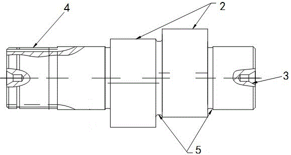
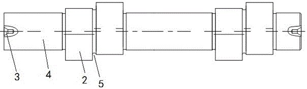
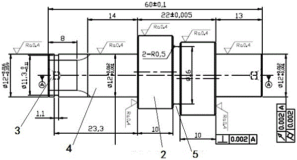
[0025] Such as Figure 1~Figure 3 As shown, a high-precision crankshaft for a reducer includes a crankshaft body, the crankshaft body is a cylinder, and at least two eccentric wheels 2 with a phase difference of 180° are provided on the crankshaft body. Both ends of the crankshaft body are provided with precision center holes 3 as the positioning reference of the spline 4 and the eccentric wheel 2. The processed spline 4 is located at the end of the crankshaft body, and the processed spline 4 is at least The two eccentric wheels 2 are located in the middle of the crankshaft body, and both ends of the eccentric wheel 2 are provided with annular relief grooves 5.

[0026] The two eccentric wheels 2 with a phase difference of 180° form a group, and the number of groups is 1 group or 2 groups.

[0027] The cross section of the relief groove 5 is a concave arc shape.

[0028] The tolerances o...


PUM


Abstract

The invention discloses a high-precision crank shaft for a speed reducer and a machining method thereof. The high-precision crank shaft comprises a crank shaft body, wherein the crank shaft body is a cylinder; the crank shaft body is provided with at least two eccentric wheels (2) with the phase difference of 180 degrees; precision top holes (3), which are used as positioning standards of a spline (4) and the eccentric wheels (2), are formed in two end parts of the crank shaft body; the machined spline (4) is located at the end part of the crank shaft body; at least two machined eccentric wheels (2) are located in the middle of the crank shaft body; annular yielding grooves (5) are formed in two ends of the eccentric wheels (2). The high-precision crank shaft for the speed reducer is simple in structure; the quantity of parts is greatly reduced; the high-precision crank shaft is easy to control, low in cost and long in service life; the precision uniformity of the crank shaft can reach no more than 0.003mm and the high-precision requirements of a robot RV speed reducer are met.

Description

technical field [0001] The invention relates to a high-precision crank shaft for a reducer and a processing method thereof, belonging to the technical field of machinery. Background technique [0002] The current crankshafts for reducers, especially the crankshafts used for robot RV reducers, require extremely high transmission precision. The crankshafts used for RV reducers have complex structures, many parts, high manufacturing costs, and failures. The rate is high, and the highest uniformity of crankshaft accuracy can only reach within 0.006mm. Contents of the invention [0003] The technical problem to be solved by the present invention is to provide a simple structure, greatly reduced parts, easy to control, low cost, long service life, and the uniformity of the crankshaft accuracy can reach within 0.003mm, which is enough to meet the high precision requirements of the robot RV reducer. A high-precision crankshaft for a reducer and its processing method. [0004] In...

Claims


Application Information

Patent Timeline
IPC IPC(8): F16C3/10B23P15/00
CPCF16C3/10B23P15/00
Inventor 杨加华徐尊善叶健
Owner JOUDER PRECISION INDAL KUSN
Why Eureka
Try Eureka