
Spring energy storage hydraulic operation mechanism and energy storage spring unit

A technology of hydraulic operation and energy storage spring, applied in electrical components, high-voltage air circuit breakers, high-voltage/high-current switches, etc., can solve problems such as difficult installation, low output characteristics of combined disc springs, and potential safety hazards.

Inactive Publication Date: 2014-11-12
STATE GRID CORP OF CHINA +2
View PDF8 Cites 11 Cited by
  • Summary
  • Abstract
  • Description
  • Claims
  • Application Information

AI Technical Summary

Problems solved by technology

The operating mechanism uses spring energy storage, which has the advantages of short stroke, large load, convenient adjustment, and easy maintenance and replacement. However, the energy storage spring unit using a combined disc spring has the following disadvantages: 1. Due to processing, installation and Due to factors such as heat treatment, the output characteristic accuracy of the combined disc spring is not high; 2. The combined disc spring needs to have high manufacturing accuracy to ensure that the output characteristics are within the allowable deviation range, and the cost is high; 3. The combined disc spring needs to be pre-compressed, and The pre-compression force is large, and it is not easy to install; 4. When the design operation power is large, the size of the disc reed is large, and there is a large safety hazard when the combination is biased

Method used


Image

  • Spring energy storage hydraulic operation mechanism and energy storage spring unit
  • Spring energy storage hydraulic operation mechanism and energy storage spring unit
  • Spring energy storage hydraulic operation mechanism and energy storage spring unit

Examples


Embodiment Construction

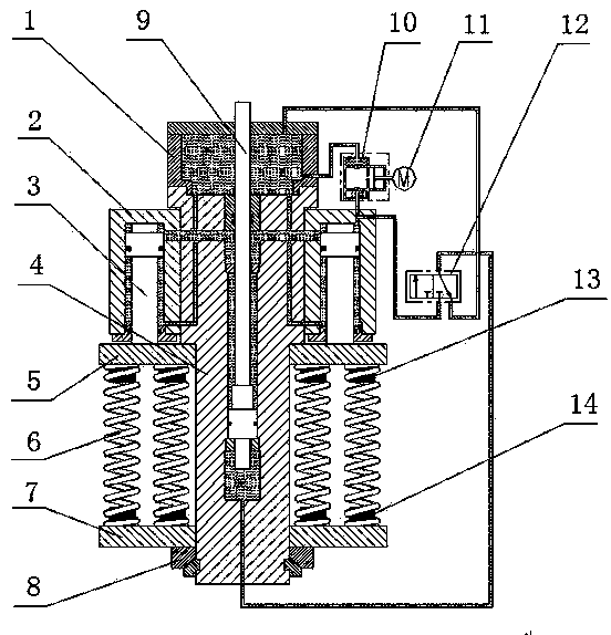
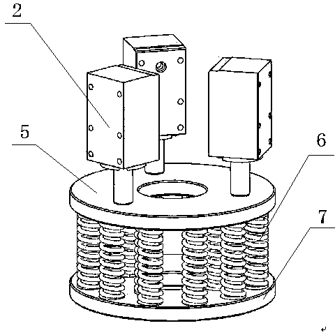
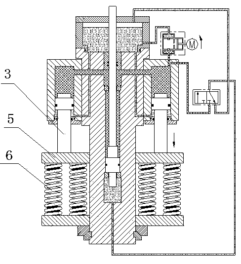
[0019] Embodiments of the spring energy storage hydraulic operating mechanism of the present invention: as Figure 1-3 As shown, it mainly includes a working cylinder 4 and an energy storage assembly, wherein the working cylinder 4 is a hydraulic cylinder, and the working cylinder piston rod 9 extends upwards from the working cylinder body as the power output shaft of the operating mechanism. The energy storage assembly is composed of an energy storage power unit and an energy storage spring unit, and the energy storage assembly stores energy when the energy storage power unit pushes the energy storage spring unit to compress. The energy storage power unit is composed of three energy storage cylinders 2, the energy storage cylinders 2 are hydraulic cylinders, and the three energy storage cylinders 2 are fixedly attached to the outer peripheral surface of the working cylinder body and evenly distributed along the circumferential direction of the working cylinder body , the uppe...


PUM


Abstract

The invention discloses a spring energy storage hydraulic operation mechanism and an energy storage spring unit. The energy storage spring unit comprises an upper press plate, a lower press plate, and an energy storage spring installed between the upper press plate and the lower press plate in an abutting mode, wherein the upper press plate and the lower press plate are arranged on a cylinder block of a working cylinder in a sleeved mode, the energy storage spring is formed by spiral compression springs which are arranged into an array between the upper press plate and the lower press plate in an abutting mode, and the center line of the spiral compression spring array coincides with the axis of the cylinder block of the working cylinder. On one hand, the machining error of a single spiral compression spring is small, a linear relationship is formed between output force and displacement, performance is stable, the influence of environment temperature is avoided in normal use, and therefore the energy storage spring unit is an ideal energy storage element; on the other hand, the multiple spiral compression springs are arranged in parallel, the slope of the characteristic curve of a single spiral compression spring can be reduced exponentially, ideal output characteristics can be obtained through reasonable design, the effect that large output force is obtained through small displacement is achieved, and the more the springs are, the smaller the length error of the spring assembly is and the higher the output precision is.

Description

technical field [0001] The invention relates to a spring energy storage hydraulic operating mechanism and an energy storage spring unit thereof. Background technique [0002] The operating mechanism is an important part of the high-voltage circuit breaker. It is mainly divided into permanent magnet operating mechanism, hydraulic operating mechanism and spring operating mechanism. Its function is to realize the opening and closing operation of the high-voltage circuit breaker. For the hydraulic operating mechanism, an energy storage spring unit should be equipped, and the energy storage spring unit mainly uses compressed nitrogen or compressed springs for energy storage. [0003] For example, Chinese patent CN100437869C discloses a spring hydraulic operating mechanism for high-voltage circuit breakers, which mainly includes a working cylinder and an energy storage assembly composed of an energy storage power unit and an energy storage spring unit, wherein the piston rod of th...

Claims


Application Information

Patent Timeline
IPC IPC(8): H01H33/34H01H33/40
Inventor 邹高鹏王亚辉雷琴王永良李海文张全民
Owner STATE GRID CORP OF CHINA
Learn More