An anti-jamming wire winding device

A wire winding and anti-jamming technology, applied in metal processing equipment, metal processing, manufacturing tools, etc., can solve the problems of low pass rate, low degree of automation, affecting the production process, etc., to avoid wire jams, high product pass rate, The effect of small length error

Active Publication Date: 2017-12-12
安徽省宁国市天成电气有限公司
View PDF5 Cites 0 Cited by
  • Summary
  • Abstract
  • Description
  • Claims
  • Application Information

AI Technical Summary

Problems solved by technology

The existing wire winding machine has a low degree of automation, which results in a large length error of the processed finished product and a low pass rate; and the mandrel in the existing wire winding machine is prone to jamming during the process of forwarding the forming part ( That is: when the mandrel is rotating, the wire wrapped around the outer periphery of the mandrel cannot be conveyed forward), so the equipment has to be stopped and the problem of wire jamming should be dealt with
Not only does it affect the production process, but the equipment needs to be continuously inspected by workers during the working process, which needs to be improved urgently

Method used


Image

  • An anti-jamming wire winding device
  • An anti-jamming wire winding device
  • An anti-jamming wire winding device

Examples


Embodiment Construction

[0023] Below, the technical solution of the present invention will be described in detail through specific examples.

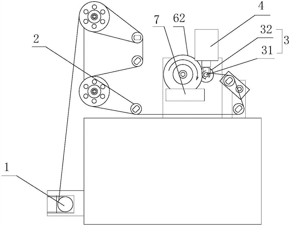
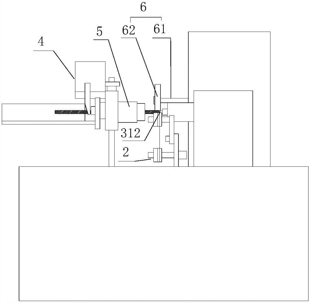
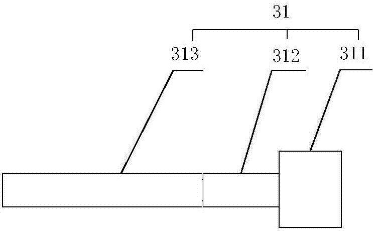
[0024] Such as Figure 1-3 as shown, figure 1 It is a structural schematic diagram of an anti-jamming wire winding device proposed by the present invention; figure 2 It is a side view of an anti-jamming wire winding device proposed by the present invention; image 3 It is a structural schematic diagram of the mandrel in an anti-jamming wire winding device proposed by the present invention.

[0025] refer to Figure 1-3 , an anti-jamming wire winding device proposed in an embodiment of the present invention, comprising: a wire releasing device 1, a wire device 2, a wire winding device 3 and a cutting device 4, wherein:

[0026] Pay-off device 1 is used for carrying out the wire-releasing action; Lead device 2 is positioned at the output end of pay-off device 1, and lead device 2 comprises the rotating shaft of rotating installation and the conductor pulley...


PUM


Abstract

The invention discloses wire-jamming-preventing wire-winding equipment. The wire-jamming-preventing wire-winding equipment comprises a paying-off device, a wire-guiding device, a wire-winding device and a cutting-off device, wherein the paying-off device is used for paying-off action; the wire-guiding device comprises rotary shafts which are rotatably mounted and wire-guiding wheels which are fixedly mounted on the rotary shafts, and coders are mounted on the rotary shafts; the wire-winding device comprises a mandrel and a driving mechanism, wherein the mandrel comprises a limiting part, a rotating part and a swinging part which are coaxially arranged, the limiting part is fixedly connected to the rotating part, and the outer diameter of the limiting part is greater than that of the rotating part; the swinging part is located at one end, far from the limiting part, of the rotating part, and one end of the swinging part is movably connected to the rotating part while the other end of the swinging part is a free end, and the outer diameter of the swinging part is equal to that of the rotating part; the driving mechanism is located at one end, far from the rotating shaft, of the limiting part, and is connected to the limiting part for driving the limiting part to rotate; and the cutting-off device is located at the output end of the wire-winding device for cutting off wires. The equipment disclosed by the invention can avoid the wire-jamming problem, and a finished piece is small in length error and high in product percent of pass.

Description

technical field [0001] The invention relates to the technical field of wire winding equipment, in particular to an anti-jamming wire winding equipment. Background technique [0002] The wire winding machine is a machine for manufacturing spiral wire (such as: spiral resistance wire). The existing wire winding machine has a low degree of automation, resulting in a large length error of the processed finished product and a low pass rate; and the mandrel in the existing wire winding machine is prone to jamming during the process of forwarding the forming part ( That is: when the mandrel is rotating, the wire wound around the outer periphery of the mandrel cannot continue to be conveyed forward), so the equipment has to be stopped, and the wire jam problem has to be dealt with. Not only does it affect the production process, but the equipment needs to be continuously inspected by workers during the working process, which needs to be improved urgently. Contents of the inventio...

Claims


Application Information

Patent Timeline
Patent Type & Authority Patents(China)
IPC IPC(8): B21F3/04B21F11/00B21C51/00
CPCB21C51/00B21F3/04B21F11/00
Inventor 钱继友冯志学赵长彬
Owner 安徽省宁国市天成电气有限公司
Why Eureka
Try Eureka