
Timber discharging machine with tailing material dragging function

A wood and functional technology, applied in the field of wood cutting machine, can solve the problems of waste, long margin, etc., and achieve the effect of improving utilization rate, reducing processing error and precise clamping

Active Publication Date: 2016-11-09
TAIZHOU EVOK MASCH CO LTD
View PDF10 Cites 11 Cited by
  • Summary
  • Abstract
  • Description
  • Claims
  • Application Information

AI Technical Summary

Problems solved by technology

[0003] But the above-mentioned blanking sawing machine also has some defects. When the wooden strip is just enough to be cut into multiple sections, the last section of the wooden strip is often slightly longer than the cut target wooden section. Cutting on the material sawing machine, because the movable clamping arm of the above sawing machine is located on the right side of the saw blade, there is a distance between the movable clamping arm and the saw blade, this distance makes the margin of the last section of the wood strip must be greater than this distance plus The sum of the clamping lengths on the clamp arm, therefore, the above-mentioned blanking sawing machine makes the margin of the last section of the wood strip cutting very long, resulting in unnecessary waste, which is unbearable when processing expensive wood.

Method used


Image

  • Timber discharging machine with tailing material dragging function
  • Timber discharging machine with tailing material dragging function
  • Timber discharging machine with tailing material dragging function

Examples


Embodiment Construction

[0030] The following are specific embodiments of the present invention and in conjunction with the accompanying drawings, the technical solutions of the present invention are further described, but the present invention is not limited to these embodiments.

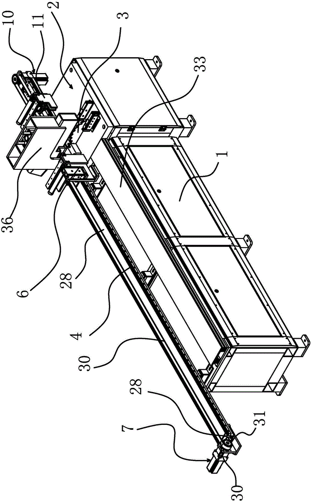
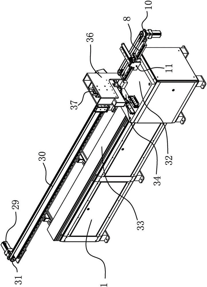
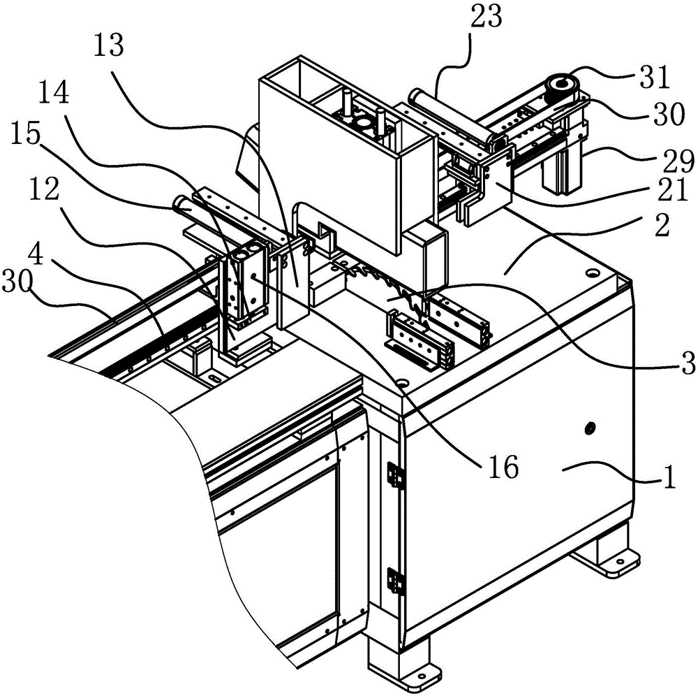
[0031] Such as figure 1 with figure 2 As shown, the wood cutting machine with tailing function includes a frame 1 with a horizontal workbench 2, and the frame 1 is provided with an electric saw 3 for cutting wood placed on the workbench 2 , the frame 1 is also fixed with a horizontal guide rail-4, and the frame 1 is provided with a strip-shaped horizontal fixed beam 28, the fixed beam 28 is fixed with the frame 1, and the horizontal guide rail-4 is fixed on the fixed beam 28 and the two Those are parallel, and the length of horizontal guide rail one 4 is 2-5 times of the length of horizontal guide rail two 8. The horizontal guide rail-4 is slidably connected with a slide block-5, and the frame 1 is provided with a drive...


PUM


Abstract

The invention provides a timber discharging machine with a tailing dragging function and belongs to the technical field of machines. The technical problem that a last section of tailing material is seriously wasted when an existing discharging sawing machine is used for cutting a batten is solved. The timber discharging machine comprises a rack. A horizontal worktable is arranged on the rack. An electric saw is arranged on the rack. A first horizontal guide rail is further fixed to the rack. A first sliding block is connected to the first horizontal guide rail in a sliding manner. The rack is provided with a first driving source used for driving the first sliding block to move along the first horizontal guide rail. A first clamping claw is fixed to the first sliding block. A second horizontal guide rail is further fixed to the rack. A second sliding block is connected to the second horizontal guide rail in a sliding manner. The rack is provided with a second driving source used for driving the second sliding block to move along the second horizontal guide rail. A second clamping claw is fixed to the second sliding block. The first clamping claw and the second clamping claw are located on the two sides of the electric saw correspondingly and can clamp the same piece of timber at the same time. According to the timber discharging machine with the tailing material dragging function, the waste of the tailing material of the timber can be reduced, and the utilization rate of the last section of tailing material of the timber is increased when the batten is cut.

Description

technical field [0001] The invention belongs to the technical field of woodworking machinery and relates to a wood cutting machine with the function of pulling tails. Background technique [0002] In wood processing, before the wood is processed as a raw material, it must be cut to match its specifications with the size of the workpiece to be formed, which inevitably requires the use of a sawing machine to cut the wood. In the prior art, manual clamping and manual cutting are mostly used for cutting plates. This method is not only inconvenient for clamping, but also time-consuming and laborious for cutting, and the processing efficiency is low. In order to solve this problem, people have designed automatic cutting machines. The Chinese patent document with the authorized announcement number CN203599632 discloses an automatic blanking sawing machine, which includes a frame and a cutting mechanism arranged on the frame. The frame is also equipped with a sheet clamping mechanis...

Claims


Application Information

Patent Timeline
Patent Type & Authority Applications(China)
IPC IPC(8): B27B5/29B27B25/00
CPCB27B5/29B27B25/00
Inventor 程楠
Owner TAIZHOU EVOK MASCH CO LTD
Learn More